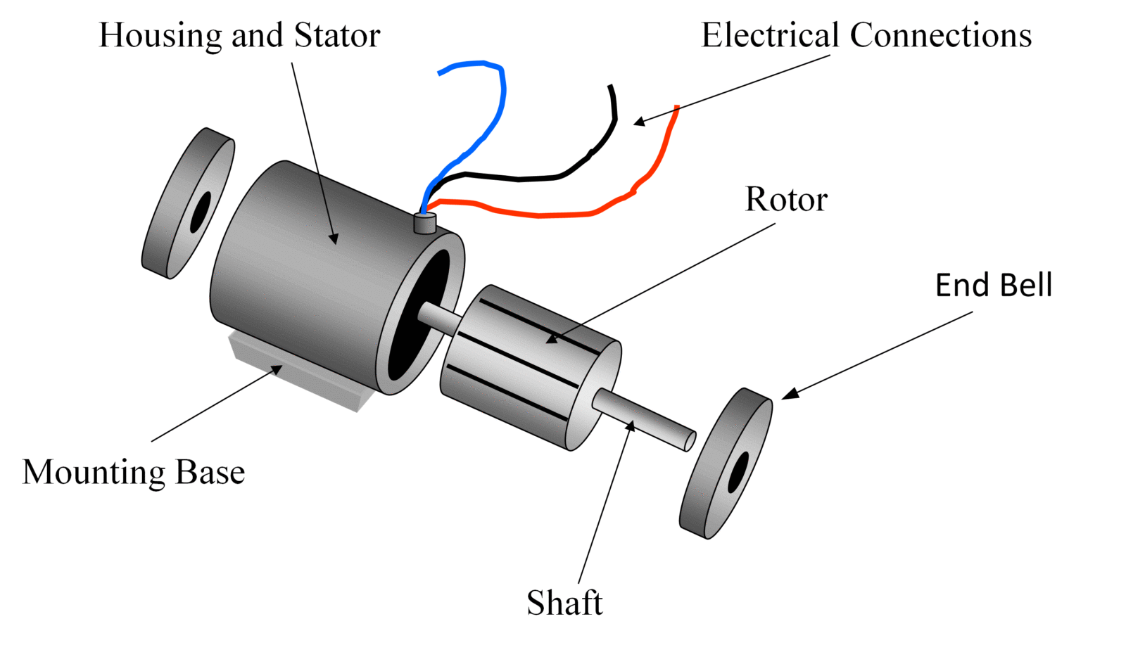
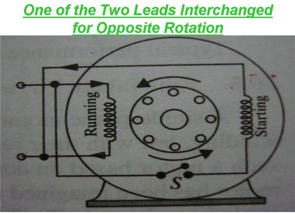
The single phase induction motor can be made to be self starting in numerous ways. Each component ought to be placed and linked to different parts in particular manner.

3 Phase Induction Motor Wiring Diagram Mustanggh 7
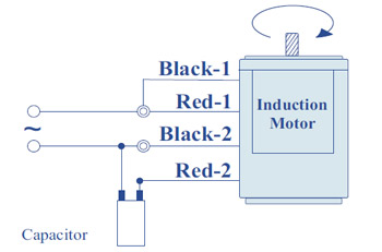
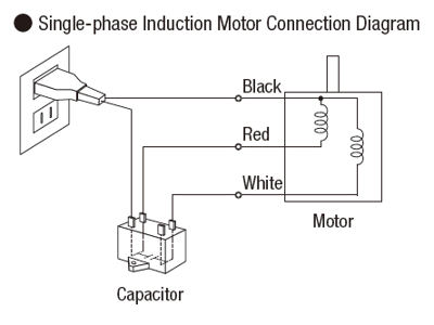
Single phase induction motor connection diagram. Wondering how a capacitor can be used to start a single phase motor. Types of single phase induction motors electrical a2z single phase induction motors are traditionally used in residential applications such as ceiling fans air conditioners washing machines and refrigerators single phase motor wiring with contactor diagram the plete guide of single phase motor wiring with circuit breaker and contactor diagram. Single phase motor wiring diagram with capacitor baldor single phase motor wiring diagram with capacitor single phase fan motor wiring diagram with capacitor single phase motor connection diagram with capacitor every electrical arrangement is made up of various unique pieces. Single phase motor wiring diagram with capacitor sources. Construction of single phase induction motor. Or single phase motor with centrifugal switch wiring diagram.
Wiring diagram for single phase motor fresh pretty single phase. Click here to view a capacitor start motor circuit diagram for starting a single phase motor. Clarke spare parts service technical help tel single phase electric motors buy online at chronos call us or. Brushes and commutators are short circuited and are placed so that the magnetic axis of the rotor winding is inclined to the magnetic axis of the stator winding. One often used method is the split phase motors. Single phase motors are inherently noisier and less smooth running than polyphase motors.
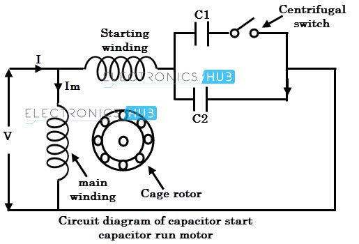
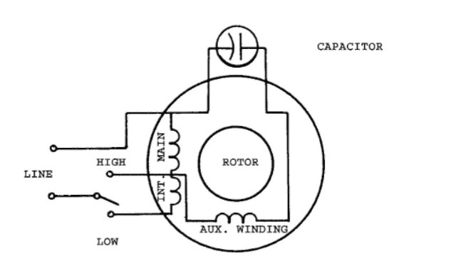
With single phase motor with capacitor forward and reverse wiring. In the single phase 36 slots winding diagram. This type of motor is designed to provide strong starting torque and strong running for applications such as large water pumps. Capacitor start capacitor run induction motors are single phase induction motors that have a capacitor in the start winding and in the run winding as shown in figure 12 and 13 wiring diagram. Single phase motor wiring diagram forward reverse collections of phase meter wiring diagram single phase motor capacitor wiring. Also read about the speed torque characteristics of these motors along with its different types.
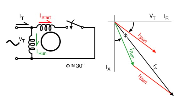
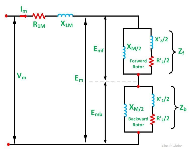
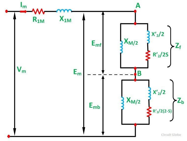
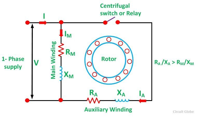
The main winding and starting or auxiliary winding connection shown. Learn how a capacitor start induction run motor is capable of producing twice as much torque of a split phase motor. A repulsion electric motor is by definition a single phase motor which has a stator winding arranged for connection to the source of power and a rotor winding connected to a commutator. Because there is a backward rotating component of flux there are pulsating torques so the torque speed curve is really just a representation of the average. A single phase induction motor is similar to the three phase squirrel cage induction motor except there is single phase two windings instead of one three phase winding in 3 phase motors mounted on the stator and the cage winding rotor is placed inside the stator which freely rotates with the help of mounted bearings on the motor shaft. Capacitor start induction motor csim circuit wiring diagram and torque speed curve.
And how to connect the both winding with one another. Single phase motor wiring diagram with capacitor start. Another method is theclarke tools clarke electric motors single phase electric motors. This post is about the single phase 4 pole induction motor winding diagram with centrifugal switch.


