I had to do this a few times with floodlights to be used outside. Use transformer if you need to.
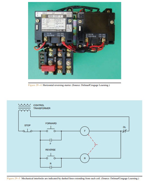
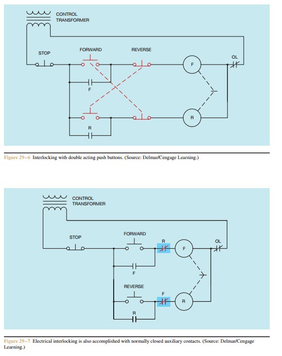
Forward Re Verse Control Developing A Wiring Diagram And
Magnetic contactor wiring diagram pdf. The people providing this information may or may not be providing completely accurate information. Use these tips to learn how to wire a contactor. This is an electromagnetic type contactor and it can operate automatically. Magnetic contactor wiring diagram data wiring diagram schematic contactor wiring diagram. Otherwise the arrangement wont function as it. This book even contains recommendations for extra supplies that you may require in order to complete your projects.
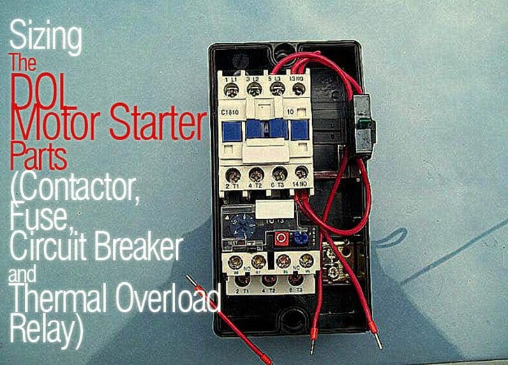
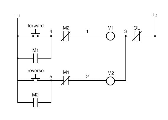
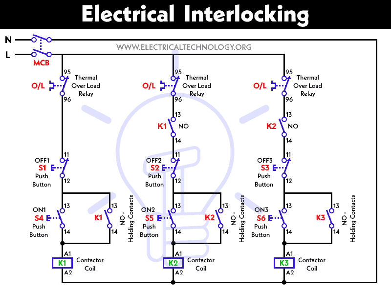
The above diagram is a complete method of single phase motor wiring with circuit breaker and contactor. It shows the components of the circuit as streamlined shapes and the power and signal connections in between the tools. Wiring diagram since wiring connections and terminal markings are shown this type of diagram is helpful when wiring the. Wiring diagram also gives beneficial recommendations for projects that might demand some extra equipment. Contactors use 120 volt standard power to energize a magnetic coil which causes a set of internal contacts to close and provide higher power to the equipment. Type s ac magnetic starters43 50 class 8536 43 50 8538 and 8539 4549 1 phase size 00 to 3 43 2 phase and 3 phase size 00 to 5 44.
It requires a small amount of control circuit to turn on and off the load. Contactors are used to provide this isolation. Therefore the operation of this contactor is safe compared to manual contactor. Magnetic contactor wiring diagram single phase. Dol starter control diagram three phase. 28 images residential electrical wiring diagrams wiring diagram schematic diagram of electric motor wiring diagram and 25 best ideas about electrical wiring diagram on 25 best ideas about.
Pdf contactor wiring diagram with timer. Contactor breakers limit switch no static control standard elementary diagram symbols. On abb contactor wiring diagram. Contactor breakers limit switch no static control. These voltages must be electrically isolated from the standard 120 volts ac. The design of this type of contactor is most advanced among all other types of contactors.
A wiring diagram is a streamlined conventional photographic representation of an electric circuit. The main and standbyemergency power supplies the neutrals of the two systems must be separated to assure proper ground fault current sensing. Starting a three phase motor. In the above one phase motor wiring i first connect a 2 pole circuit breaker and after that i connect the supply to motor starter and then i do cont actor coil wiring with normally close push button switch and normally open push button switch and in last i do connection between capacitor. Collection of contactor wiring diagram pdf. The diagram symbols in table 1 are used by square d and where applicable conform to nema national electrical manufacturers a ssociation.

