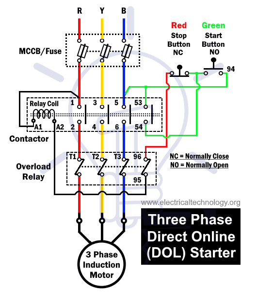
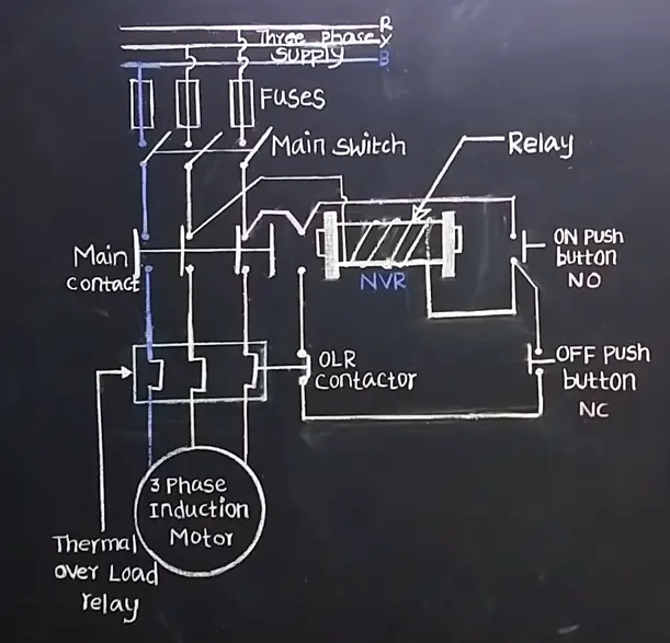
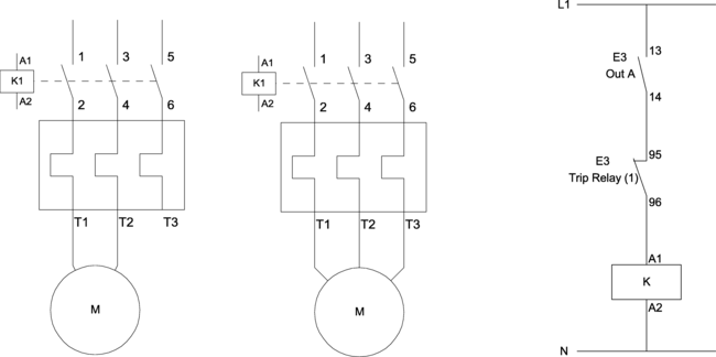
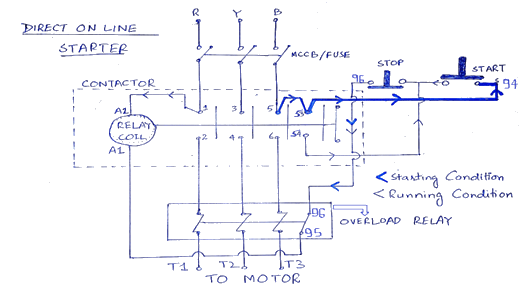
We have to use all 3 poles of the overload relay otherwise the imbalance due to the current flow in only 2 of them will cause unnecessary tripping. The main heart of dol starter is relay coil.

240 Transformer Wiring Diagrams Wiring Diagram Source
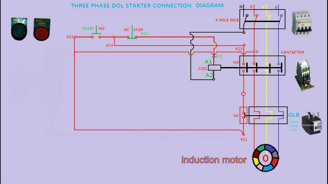
Single phase dol starter wiring. Direct on line dol motor starter 3 wiring of dol devices for 230v single phase with 230v coil wiring of additional start stop devices on dol devices for 400v 3 phase with 230v coil additional start and stop stations can be wired to the dol control circuit. Despite this direct connection no harm is done to the motor. And one wiring is called controlling wiring. And if you want to learn about the dol starter wiring for single phase then read the below post. In principle the start buttons should be momentary normally open device and wired in. In the above three phase dol starter wiring diagram.
Normally it gets one phase constant from incoming supply voltage a1when coil gets second phase relay coil energizes and magnet of contactor produce electromagnetic field and due to this. Between the mains supply terminals and motor terminals the dol starter main terminals are connected and with the two terminals of the three phase power supply as described in figure 1 the control circuit is energized. A dol starter or direct on line starter or across the line starter is a method of starting of a 3 phase induction motorin dol starter an induction motor is connected directly across its 3 phase supply and the dol starter applies the full line voltage to the motor terminals. A single phase dol motor starter can be designed using the same components as shown in following diagram. Note that the single phase dol starter wiring diagram is also like this. The above diagram is a complete method of single phase motor wiring with circuit breaker and contactor.
Working principle of dol starter. You can also connect timer limit switches float switch reverse forward remote switches and other controlling device. Direct on line starter wiring diagram. Therefore reversing of single phase motors is not covered here. I dol starter wiring connection with start and stop buttons are shown in the above figure 1. Therefore wiring a reversing starter for single phase operation is possible but can only be advised for those who fully understand the wiring techniques of their specific single phase motors and have the knowledge and experience to work out how to apply that to the reversing starter.
In the below dol starter wiring diagram i shown a molded case circuit breaker a magnetic contactor normally open push button normally close push button switch thermal overload relay motor trip indicator and 3 phase motor. What is dol starter. In the above one phase motor wiring i first connect a 2 pole circuit breaker and after that i connect the supply to motor starter and then i do cont actor coil wiring with normally close push button switch and normally open push button switch and in last i do connection between capacitor. Single phase motor dol starter connection diagram. Wiring diagram of dol starter. Single phase dol starter wiring diagram.


