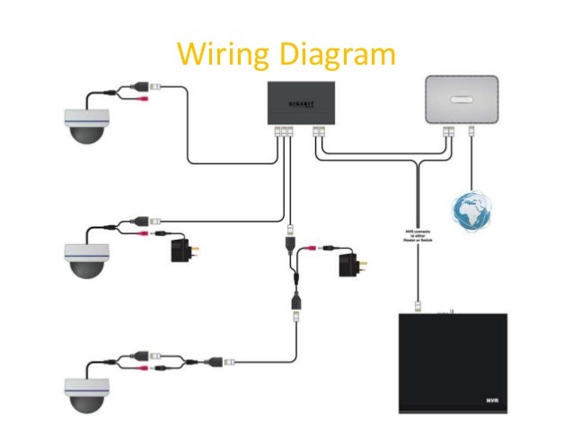
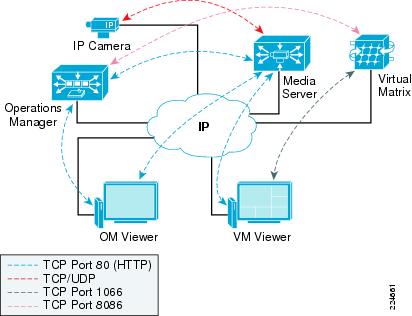
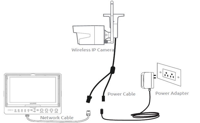
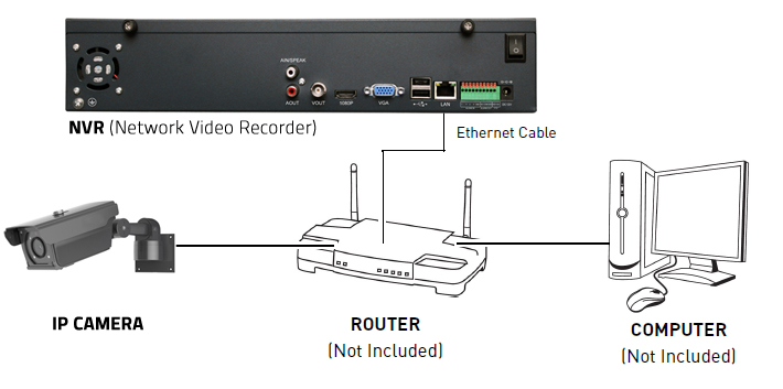
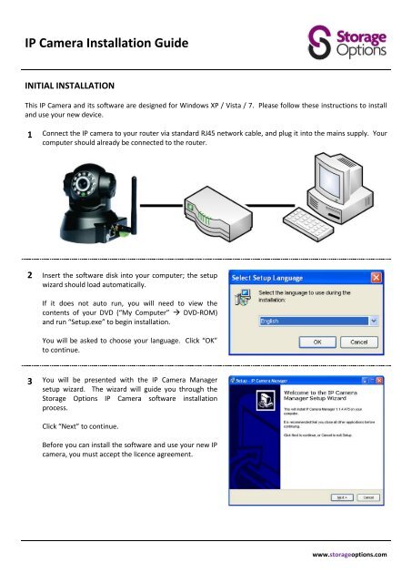
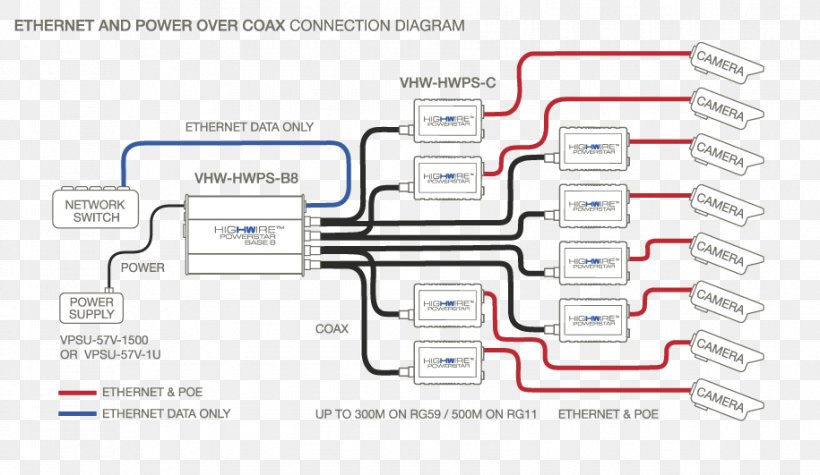
Ip camera installation wiring diagram with nvr system. Poe ip camera wiring diagram poe ip camera wiring diagram every electric structure is composed of various diverse components.

Why Does No One Set Up Their Ip Cameras In This Fashion Ip
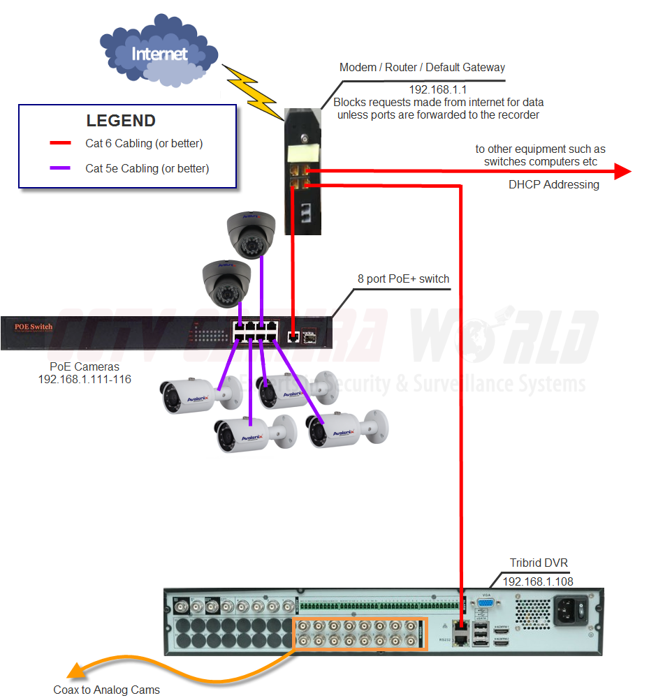
Ip camera connection diagram. Then follow the diagram below to connect. Cctv installation and wiring options. Take a look at the picture below on the left side its the rj45 pinout t 568b and the right side the dahua ip camera poe pinout color coded wiring diagram. Home router ip camera network setup. The hikvision cameras dont use the standard cat5cat5ecat6 color coded wiring. Optional wiring connection of dvr security cctv camera.
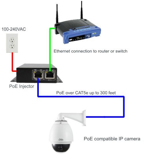
It shows the elements of the circuit as simplified forms and the power as well as signal links between the tools. To connect a new connector rj45 jack to the hikvision ip camera refer to the diagrams below. It reveals the parts of the circuit as simplified forms and also the power and also signal connections in between the devices. Poe ip cctv camera bullet dome or ptz cameras monitor lcd pc laptop etc power supply adopter power splitter and other related cables and connectors such as vga cables rj45 etc. The following instructions are for the android app. The diagram below shows a laptop connected to a poe injector which is connected to an ip camera via a network cable also known as utp cable.
Otherwise the arrangement will not function as it should be. As you can see im not using a router on the diagram as per the article title. A wiring diagram is a streamlined traditional pictorial depiction of an electrical circuit. Im sure you know what a laptop and an ip camera are but perhaps is the first time you see a poe injector. Collection of ip camera wiring diagram. Ip camera connection diagram for the first time to connect you need to connect the camera to the routers lan port using a network cable.
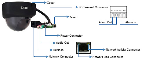
Today there are a lot of options when it comes to choosing a quality cctv security system. Each component ought to be placed and connected with different parts in particular way. One thing all of these options have in common is you will probably have to run some sort wire to the cameras. Reolink rlc 410w wifi cctv network diagram when the wifi ip camera network setup is done you are free to remove the ethernet cable. Make the connection as shown on the illustration. For example grey wire goes to pin 8 brown wire goes to pin 2 blue goes to pin 1 and so on.
You can set up the router ip camera network via either ethernet cable connection for traditional wireless cameras and wired cameras or wireless connection for wire free cameras. Assortment of ip camera wiring diagram. Pro series cameras and value series cameras have differently colored wires so each camera has its own wiring diagram. A wiring diagram is a simplified traditional photographic representation of an electrical circuit. Instructions for the ios version are slightly different. You may decide to go with a traditional analog system hd sdi hd cvi or even an ip network based security products.


