I was hoping for a little direction. You can get them at places like napa or here.
Automotive Flashers Gtsparkplugs
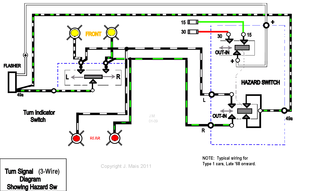
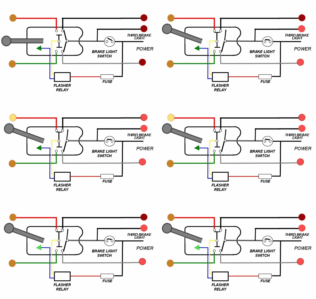
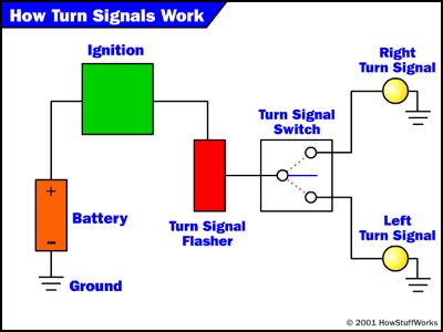
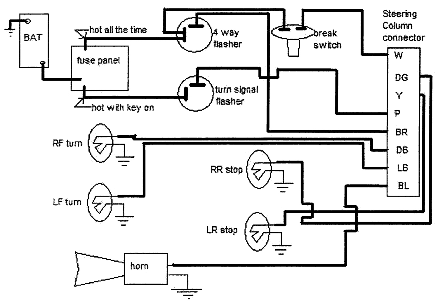
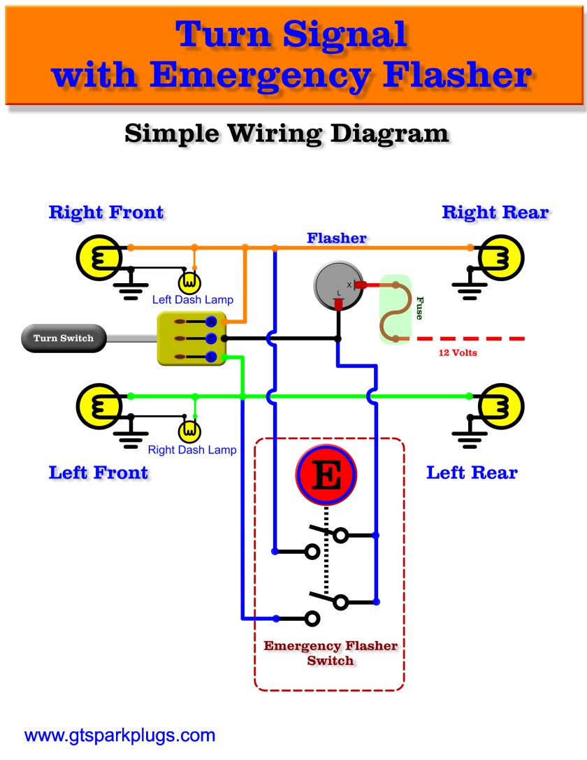
Simple turn signal wiring diagram. A quick and cheap way that works just as good is a tail light wiring converter for trailers. They look like this. It shows the parts of the circuit as simplified forms and also the power and also signal links in between the devices. The power goes through a fuse panel into the thermal flasher. Simple turn signal flasher wiring diagram the above flasher wiring diagram shows how you would connect up the simplest of turn signal switch flasher and bulbs. Many good image inspirations on our internet are the best image selection for simple turn signal wiring diagram.
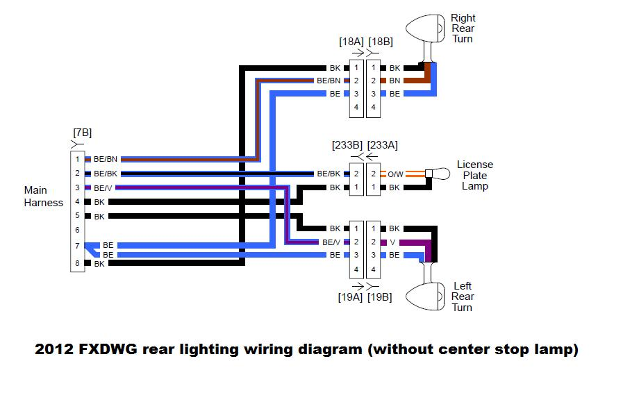
They will combine the brake wiring and the turn signal wiring so they will work. Some have the tail light wire running through them 4 wire into 3 wire and some dont 3 wire into 2 wire. Lets take a look at how the turn signal circuit is hooked up. A wiring diagram is a streamlined standard pictorial depiction of an electric circuit. The turn signal circuit gets power when the ignition key is on. Variety of universal turn signal wiring diagram.
Gm turn signal diagram wiring diagram datasource simple turn signal wiring diagram we collect lots of pictures about simple turn signal wiring diagram and finally we upload it on our website. Jul 29 2017 hi my names anthony and im looking to buy turning signals for my electronic scooter but i dont know how to go about it. Can you tell me what ill be needing to make this attach. My scooter doesnt have one already so im not just replacing parts but installing the entire thing. From there it goes to the stalk on the steering column. Note that some cars have multiple bulbs some have single bulbs with multiple filaments so it can be a turn light and a parking light but still only use one bulb.
