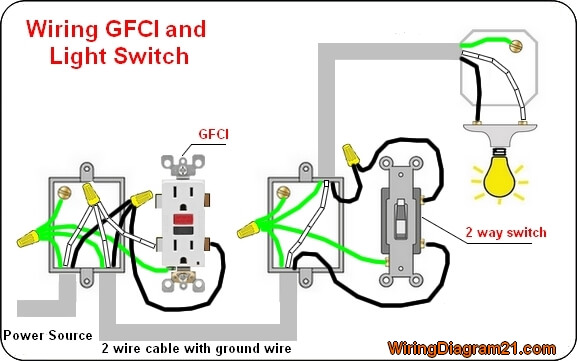
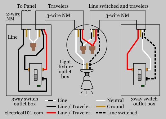
You just need to keep track of the wire designations and make the spliced connections to support the devices you are connecting to. Multiple receptacle outlets can be connected with lighting outlets as depicted in the above light switch wiring diagram.
Light Switch Wiring Diagrams Do It Yourself Help Com
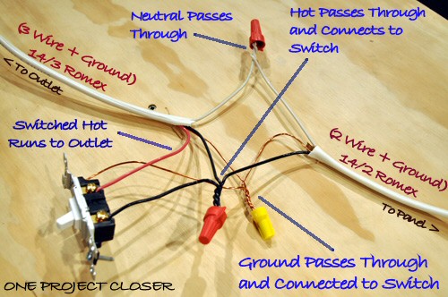
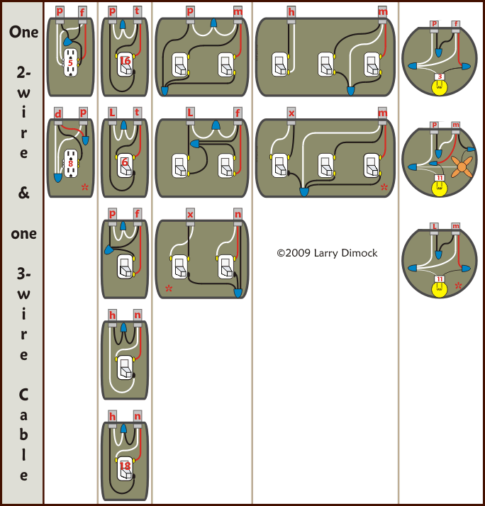
Wiring diagram light switch and receptacle. The back wire feature still relies on the terminal screw to clamp the wire but you dont have to bend the wire around the screw. Fishing in a wire from the receptacle to the light fixture is fairly easy so this is how you would wire the switchreceptacle combo device in this situation. When the wiring connections are made properly there is always the possibility for the wiring in a switch box to provide power for a light switch while providing power to outlets on the same circuit. This topic explains 2 way light switch wiring diagram and how to wire 2 way electrical circuit with multiple light and outlet. The hot and neutral terminals on each fixture are spliced with a pigtail to the circuit wires which then continue on to the next light. If you are fixing more than one outlet the wiring can be done in parallel or in series.
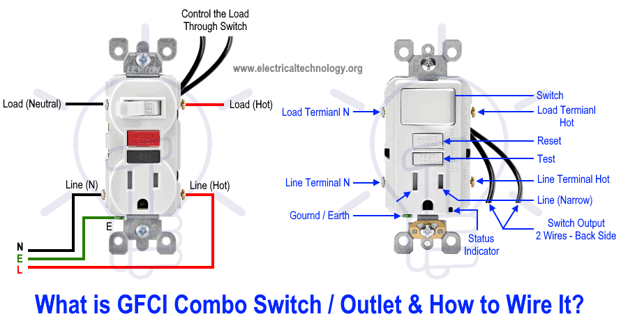
The light onoff operation can be controlled through the gfci switch while the ordinary outlet is directly connected to the gfci load terminals. The source is at the outlet and a switch loop is added to a new switch. Dont install a three slot receptacle without a ground. Switched split outlet wiring diagram for controlling the half of two duplex electrical receptacles by a wall switch without a neutral conductor. Just strip it push it in and tighten the screw when wiring a switch. This diagram illustrates wiring for one switch to control 2 or more lights.
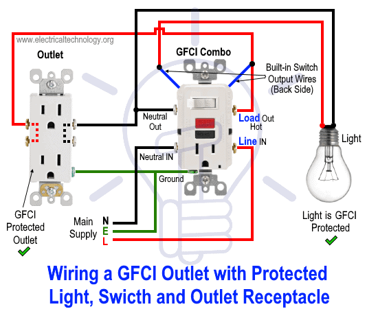
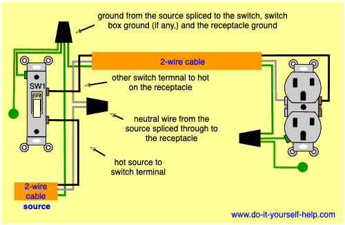
Multiple light wiring diagram. The hot source wire is removed from the receptacle and spliced to the red wire running to the switch. In this special case wiring diagram both light and ordinary outlet is connected to the load terminals of gfci. How to wire an electrical outlet wiring diagram wiring an electrical outlet receptacle is quite an easy job. The black wire from the switch connects to the hot on the receptacle. The source is at sw1 and 2 wire cable runs from there to the fixtures.
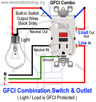
Wiring a gfci outlet with combo switch outlet receptacle light switch. In this gfci outlet wiring and installation diagram the combo switch outlet spst single way switch and ordinary outlet is connected to the load side of gfci. Also shown is the half of the receptacle that is live at all times and the tab that must be cut in order to split the receptacles. This wiring diagram illustrates adding wiring for a light switch to control an existing wall outlet. My light switch wiring diagrams may be helpful to you. Which we dont recommend using for wiring a light switch.
Wiring a gfci combo switchoutlet with protected light outlet receptacle. Light switch wiring diagram with power from the circuit breaker panel going to an electrical receptacle outlet and then continues to the next outlet and then to a single pole wall switch and then to another outlet. Scenario 2 a typical example of this situation is if you had the same scenario as above but with a 3 wire circuit such as in a kitchen split receptacle and wanting to add some under. It means all the connected loads to the load terminals of gfci are protected.


