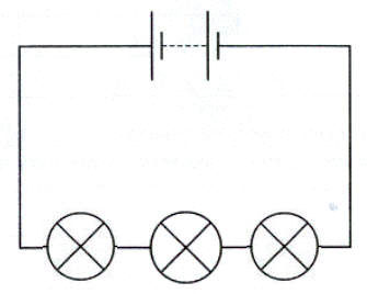
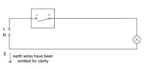
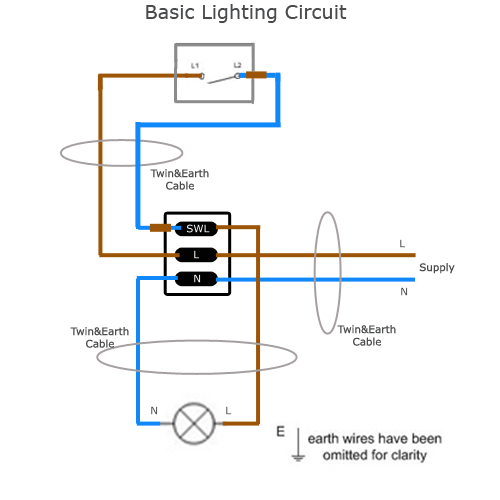
Creative craft supplies since 1949. A wiring diagram is a simple visual representation of the physical connections and physical layout of an electrical system or circuit.
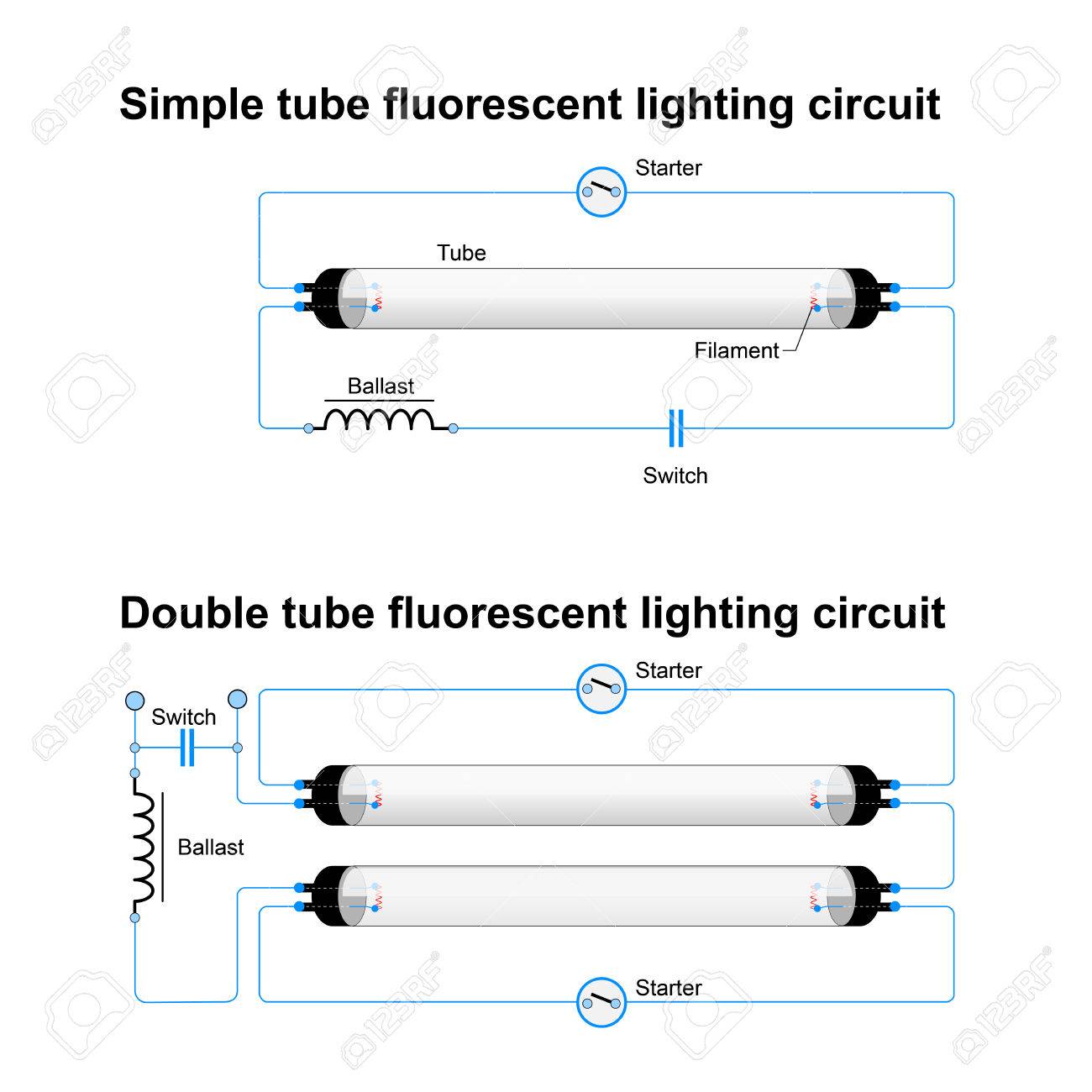
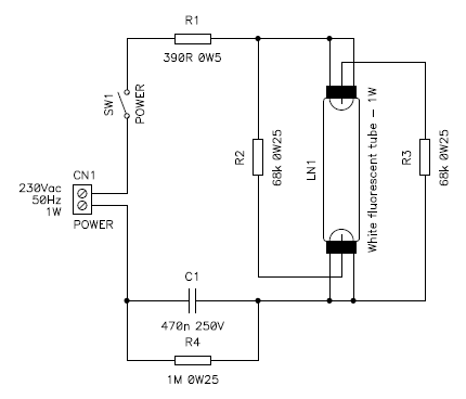
Single And Double Tube Fluorescent Lighting Circuit Simple Vector
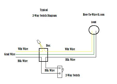
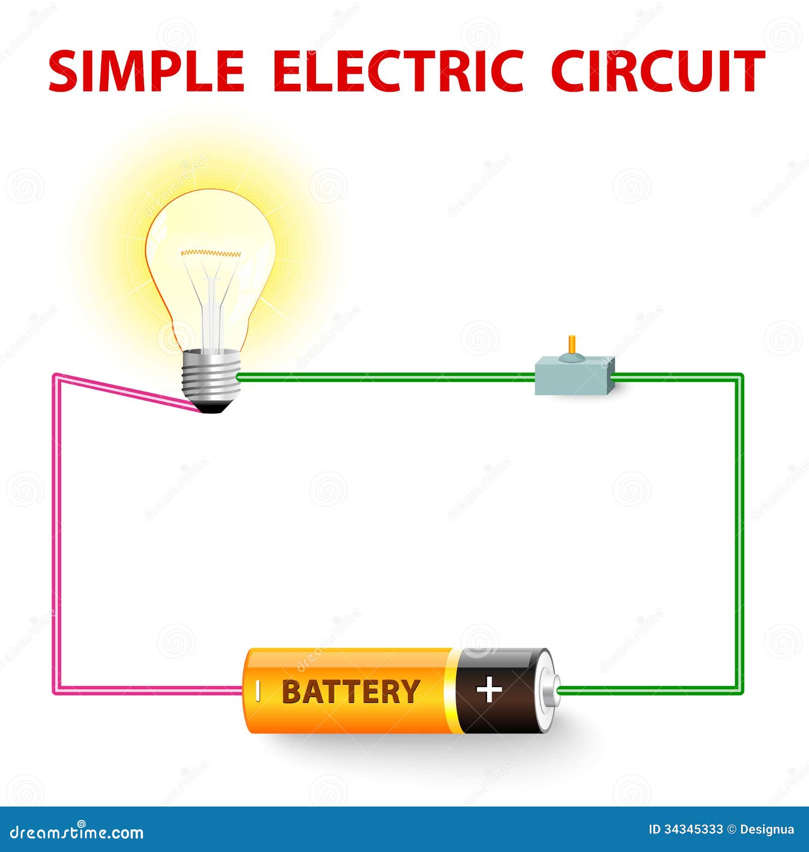
Simple lamp wiring diagram. Stair case wiring circuit diagram or how to control a lamp from two different places by two 2 way switches. It shows just how the electrical cables are interconnected and could additionally show where fixtures and components may be attached to the system. In this case you will need a set of wiring taps and a pair of pliers. Basic lamp assembly guide follow the illustrations below to see the basic parts and assembly steps required to make a typical lamp. 4 pin trailer wiring diagram. So i can help you regarding this.
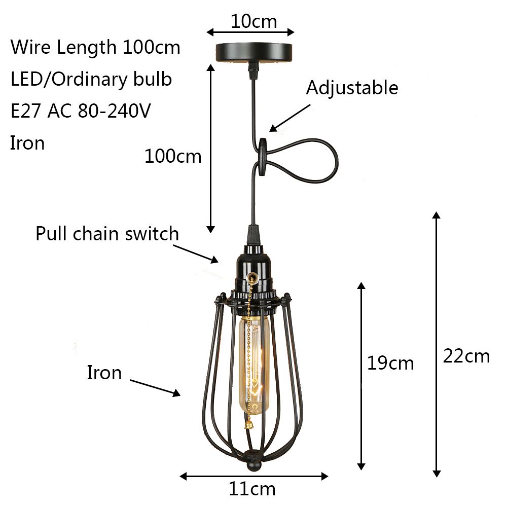
This is a wiring diagram for a vintage floor lamp with 4 bulbs one main bulb and 3 peripheral and usually smaller bulbs. Types of lighting stage lighting home lighting lighting design home electrical wiring electrical installation light bulb bases lamp bases commercial lighting. A simple guide for wiring or re wiring lamps and similar lighting projects. Electrical outlet 2 way switch wiring diagram how to wire light with receptacl. Easy simple explanation. Wiring a vintage floor lamp switch.
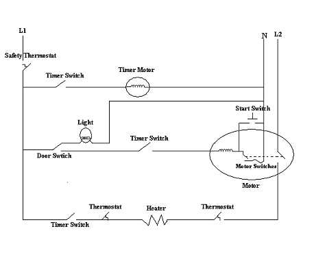
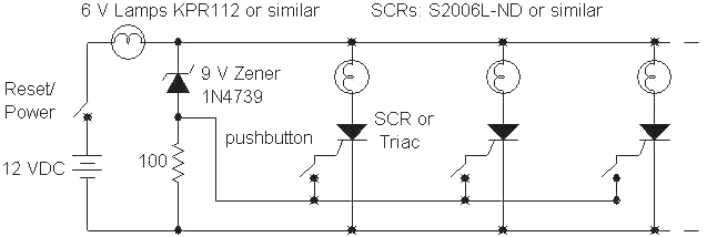
It shows how the electrical wires are interconnected and can also show where fixtures and components may be connected to the system. Thanks of sharing your electrical knowledge please give the eod crane control wiring diagram of four and five stage resistance box. Above we have describes the main types of trailer wiring diagrams. A wiring diagram is a simple visual depiction of the physical links as well as physical design of an electric system or circuit. To connect the electric system of your trailer to the vehicle you will be using special connector. Wiring diagram is a technique for describing configuration of electrical equipment installation for example installation of electrical equipment in substation in cb from panels to cb boxes which include aspects of telecontrol telesignaling telemetry all aspects that require a wiring diagram which is used to locate faults add equipment new auxillary etc.
Below is the generic schematic of how the wiring goes. The main bulb threads into a standard socket with an integrated switch and the three peripheral bulbs are wired to a single switch usually located near the central socket. Light bulb sizes shapes and temperatures charts bulb reference guide.

