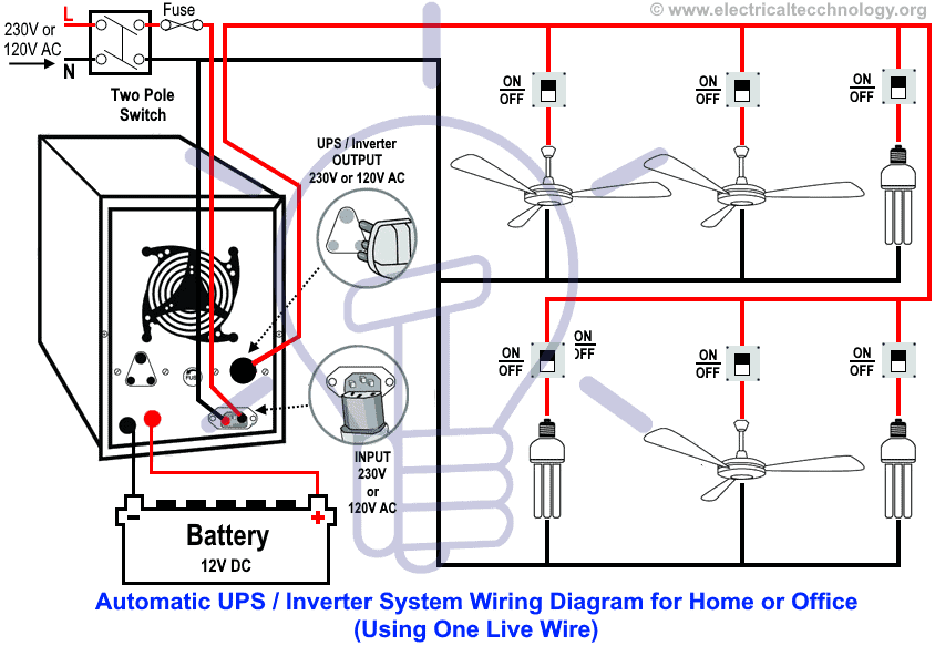
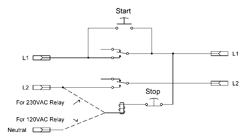
The switch of the encoder is connected to digital pin d10 and is also. 1b circuit diagram for one pole of a 3 pole 4 way switch in.
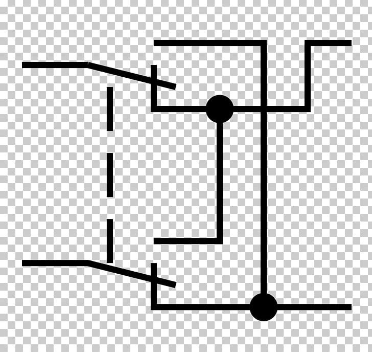
Electrical Switches Changeover Switch Circuit Diagram Wiring
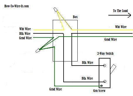
Rotary switch circuit diagram. A wiring diagram is a simplified traditional pictorial depiction of an electric circuit. Collection of rotary switch wiring diagram. The first two pins are ground and vcc which is connected to the ground and 5v pin of the arduino. These contain two or more input terminals called poles. Rotary switch 2 position 8 pole 60 25 a 400 v oc25 series check stock lead times more stock available week commencing 100820 contact me when back in stock. It shows the components of the circuit as streamlined shapes and also the power and signal connections in between the devices.
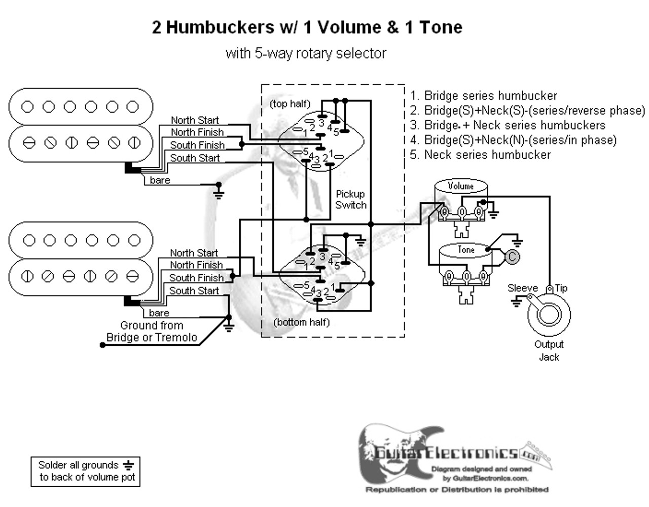
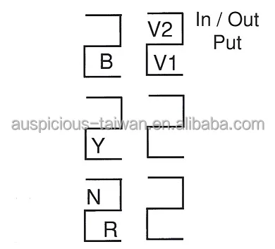
Rotary switches come in different pin arrangements some of the most. Some rotary switches contain more than one circuit. A wiring diagram is a streamlined conventional pictorial representation of an electric circuit. It shows the elements of the circuit as simplified forms and also the power as well as signal links in between the devices. A rotary switch connects several devices to an electric source. 1b for a circuit symbol.
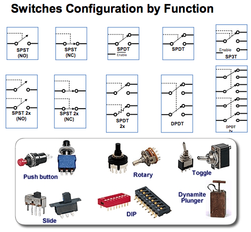
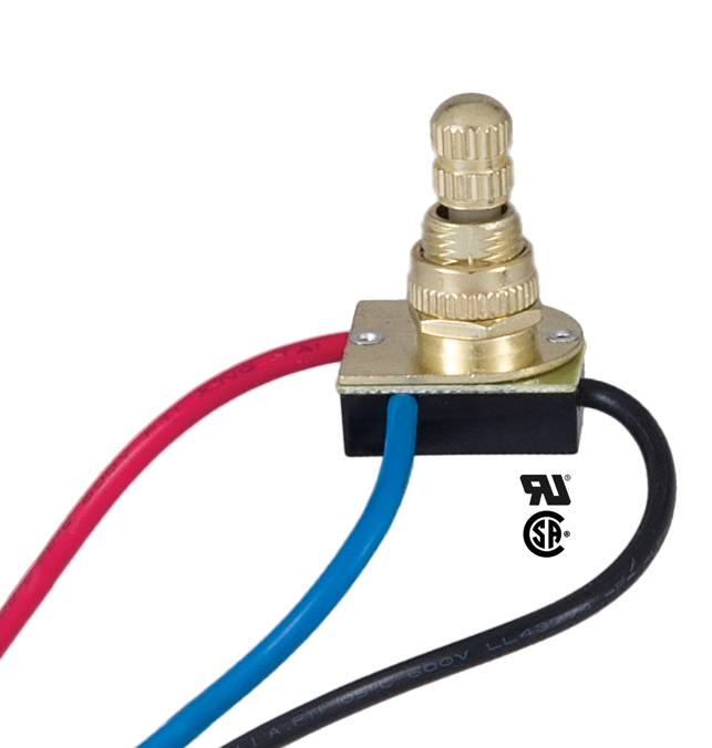
It reveals the elements of the circuit as streamlined forms as well as the power and signal links between the gadgets. 1a a typical rotary switch fig. A single pole switch controls just one circuit. Variety of 4 position rotary switch wiring diagram. A rotary switch is a switch in which the contacts are changed when the spindle is rotated in either a clockwise or an anticlockwise direction. A switch pole refers to the number of separate circuits that the switch controls.
49 lovely how to install portable generator to house wiring transfer. How to use a rotary switch what is a rotary switch. 1a for a picture of a rotary switch and fig. This is electronic rotary switch circuit using digital ic use a single switch choose a function of external control circuit has 9 positionsbegin with press the switch s1 the output signal from pin 2 of ic1 as high at all and the pulse signal to ic2 the output at pin 3 is high as well. A double pole switch is like two separate single pole switches that are mechanically operated by the same lever knob or button. The electricity enters the rotary switchs input terminal and the switch sends electricity to the output terminal selected.
1a for a picture of a rotary switch and fig. A rotary switch is a switch in which the contacts are changed when the spindle is rotated in either a clockwise or an anticlockwise direction. A double pole switch controls two separate circuits. The complete circuit diagram for interfacing rotary encoder with arduino is shown in the picture below the rotary encoder has 5 pins in the order shown in the label above. Electric tarp switch wiring diagram download rotary switch wiring diagram ge cre auto electrical wiring.


