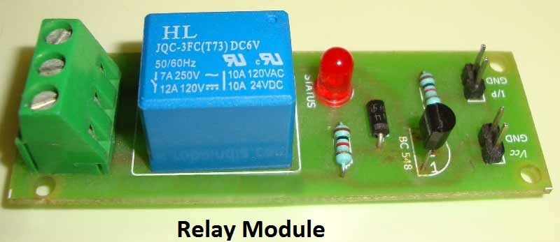
The circuit is using a dpdt relay at the output from which you can connect your home appliances to operate them wirelessly like fan lamp etc. The infrared remote control switch is divided into two sections.

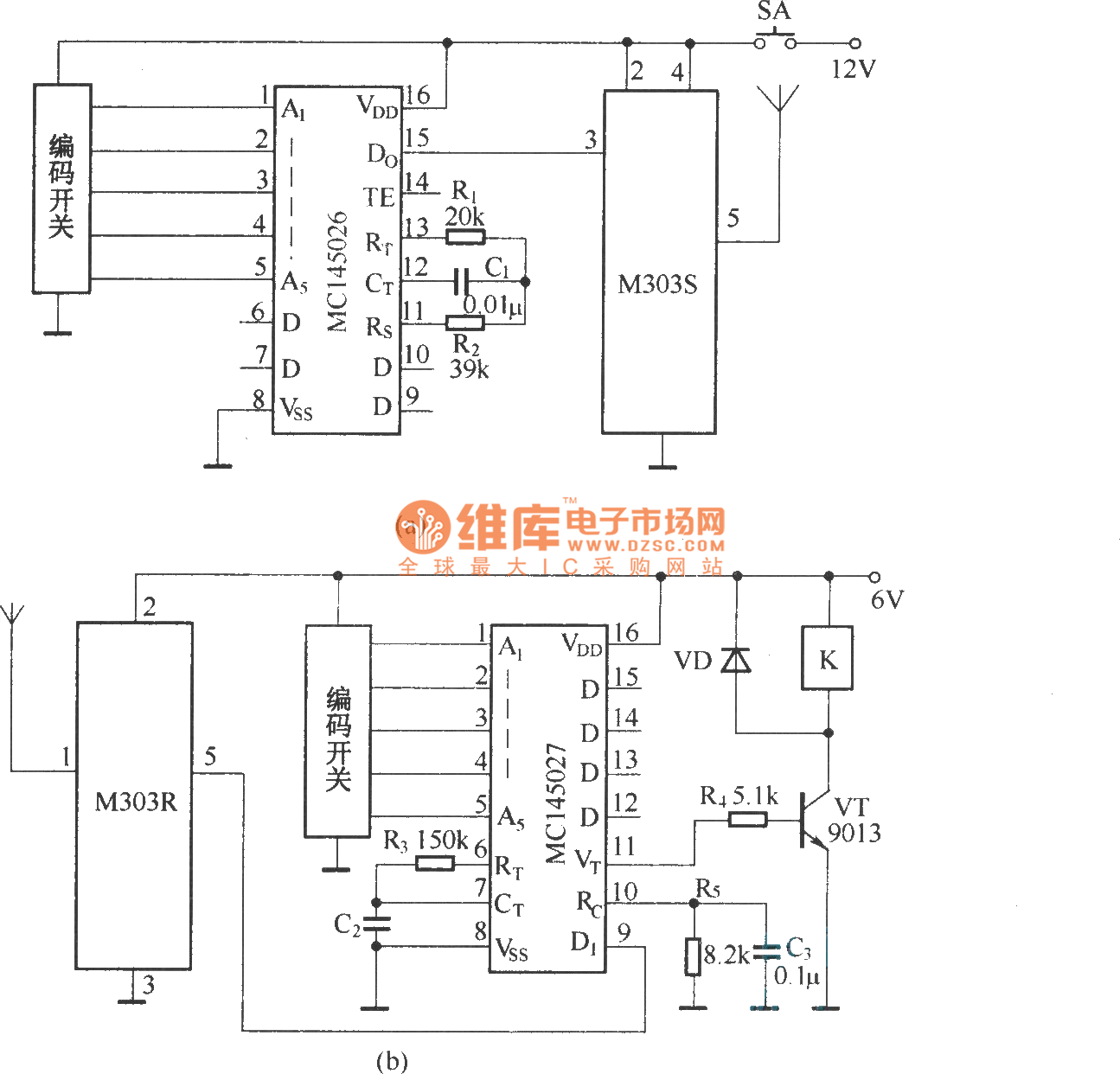
Rf Remote Control Relay Switch Circuit Diagram
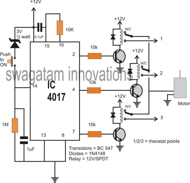
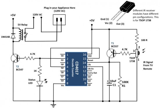
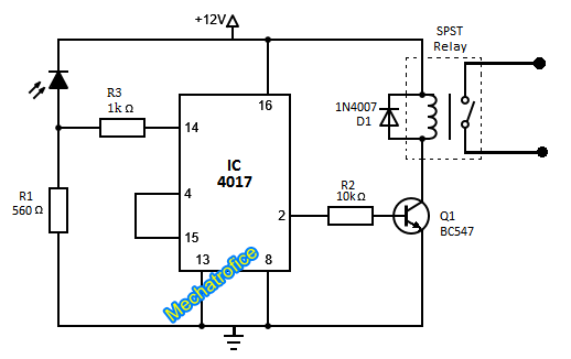
Remote control relay switch circuit diagram. This current is given to the inverting input of 3130 ic which will get triggered by this current and give amplified output. We uses normal switch in our daily life and after a long time used to these swithing system we can no more interested in that. In the receiver section there are 3 photodiodes which will detect the infrared signals from the receiver and produce leakage current to the capacitor c1. In this remote controlled switch circuit we are using tv remote to onoff the ac light by pressing any button of remote and using the tsop1738 at receiver end. We have used ic 4017 to convert it into a push on push off switch. Ir remote controls switch circuit.
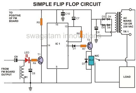
The main components of this ir remote control switch are ca 3130 operational amplifier and 4018 counter. Transmitter section and receiver section. Circuit diagram of infrared remote control switch. Here we are using a 1n4007 diode to protect the relay from any shorts or negative feedback. The schematic pcb gbr files are provided at the end. This is the very simple circuit diagram of ir remote control switch.
This is a good solution for a unique and so interesting idea to wireless switching system to control the home appliance. Circuit diagram ir remote control switch using cd4017 download project files. Ir doorbells security alarms. The ca 3130 op amp is a bicmos operational amplifier and it has a high input impedance a low input current and a high speed performance. Remote control of home appliances. Receiver circuit is connected to ac appliance via relay so that we can control the light remotely.
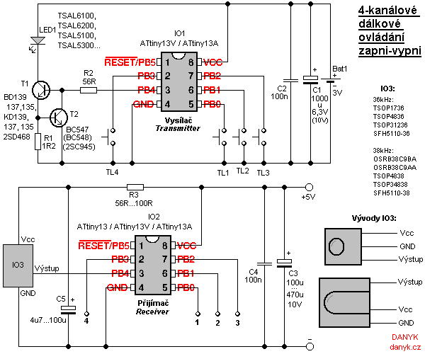
This is a project of an rf remote control relay switch circuit.
