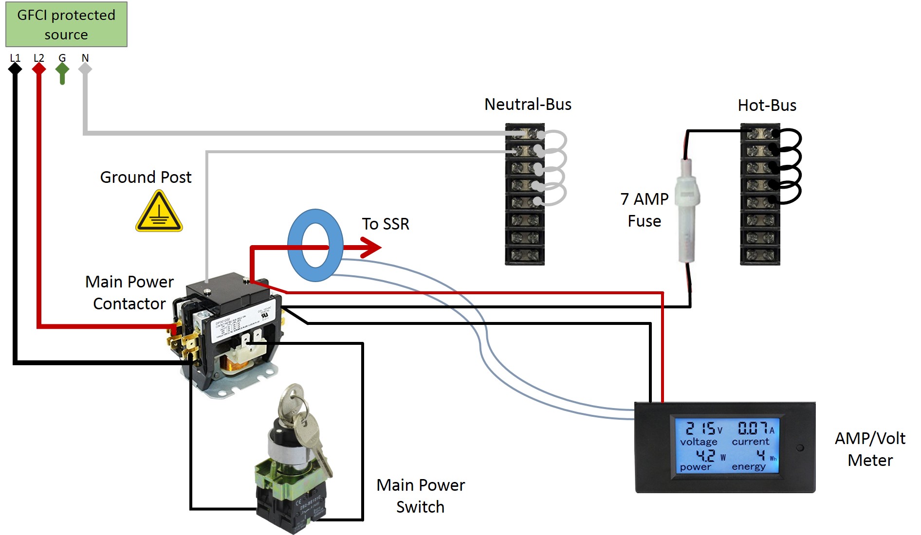
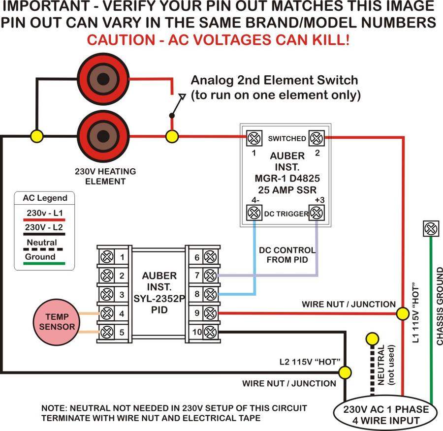
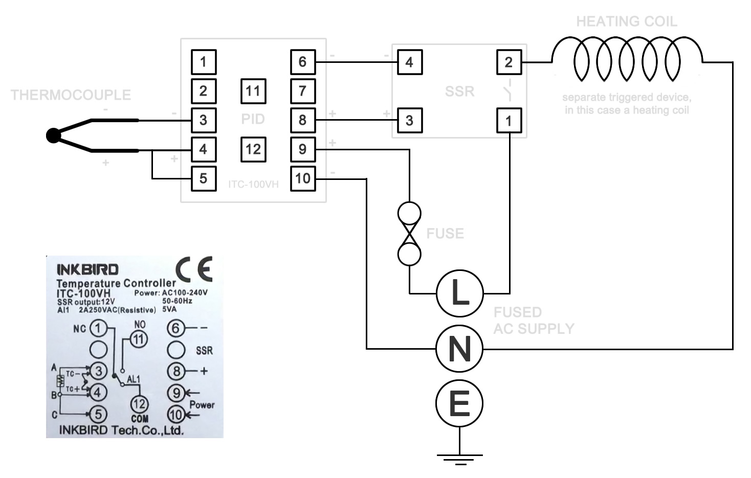
Does anybody have a wiring diagram for a 240v control panel that includes a pid 40a ssr 5500w element 240v pump and receptacles for the element and pump. Pid wiring diagram wiring diagram for the inkbird itc 100vh pid.

Wiring The Pid Controller
240v pid controller wiring diagram. Please remember this diagram relates only to the inkbird itc 100vh pid. The circuit is designed for a 240v system with a total oven draw no more than 30amps. This will all be plugged into a dedicated 30 amp l6 30r wall receptacle connected to a 240v 30a gfci breaker. In my case im in the uk and the standard mains power is 230 volts ac. This kit includes each of the following. Other makes and models will need to be wired differently.
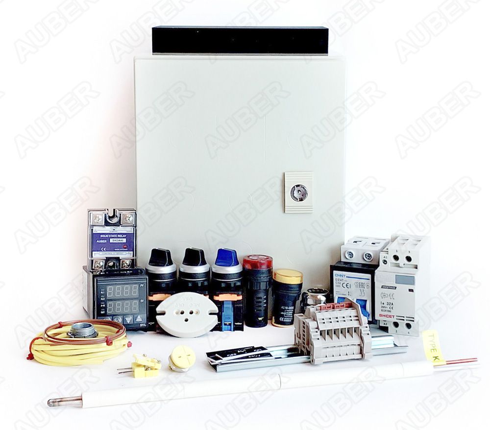
Wiring diagram and other installation manuals are available after purchase. Barley and hops brewing 5655 views. Wiring diagram and punching specification are available after purchase. Wiring a 120 volt 20 amp pid controller duration. If you know how to translate it wiring everything up is quite simple. This kit includes each of the following.
It has a pid controller and an independent timer. In addition to a pid controller with built in timer it also has a flashing buzzer for high temperature alarm. The power source is the mains in your neck of the woods. The circuit is designed for us split phase 240v power supply and you can connect up to four 3000 watt elements. 12x10x8 wall mount enclosure with knockouts for all holes needed. If you are using a 3 wire sensor then it connects to terminals 3 4 and 5.
I would also like to have a switch and led for both the element and pump. Lets start with the temperature sensor. In the instruction manual for your pid and possibly on a sticker on the case will be a wiring diagram like the one above. Wiring 120v pid and theory part 2 duration.


