This vehicle is designed not just to travel one location to another but also to carry heavy loads. Pilot brake controller does not show trailer connected when connected to a 2000 dodge ram 1500.

Installation Of A Trailer Brake Controller On A 2008 Chevrolet Silverado Etrailer Com
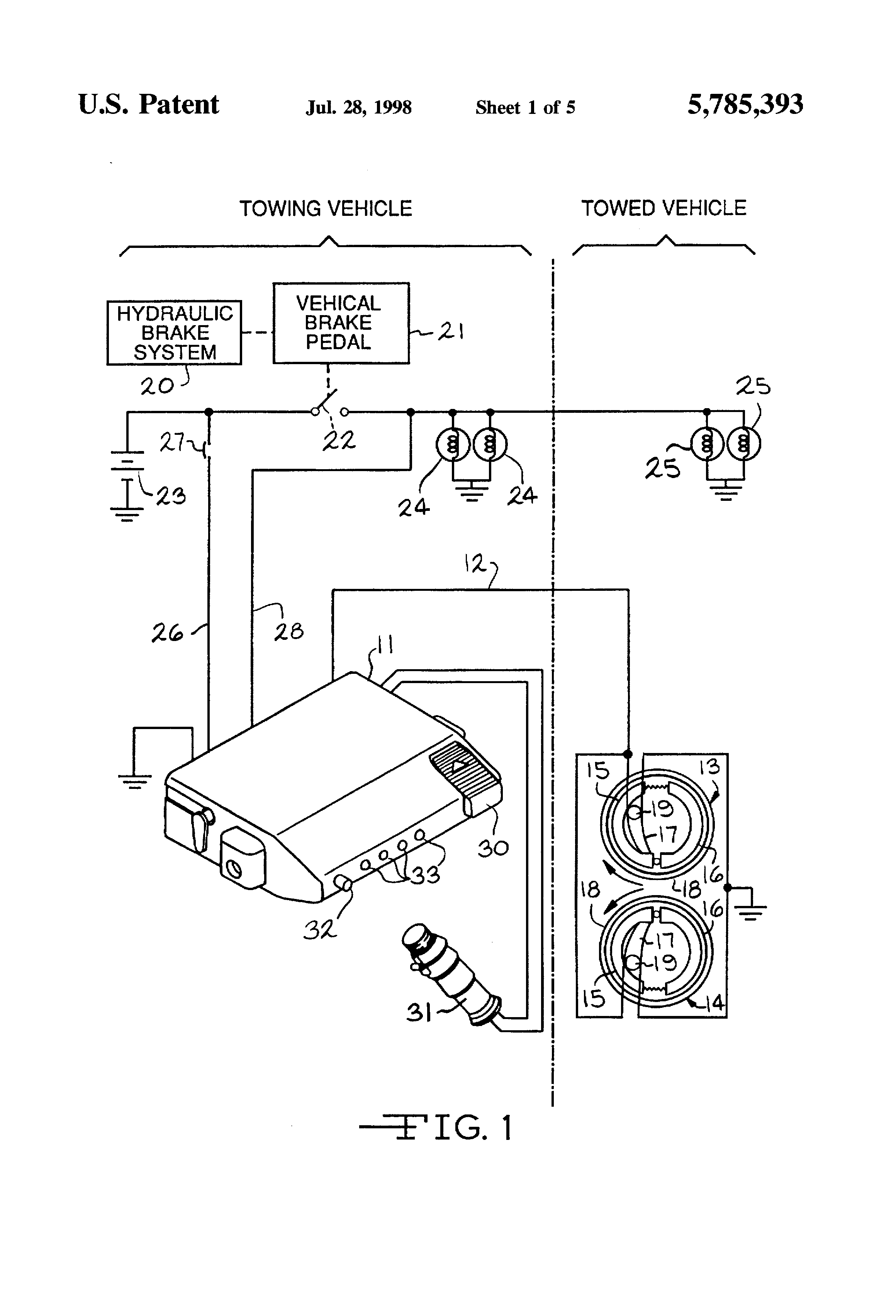
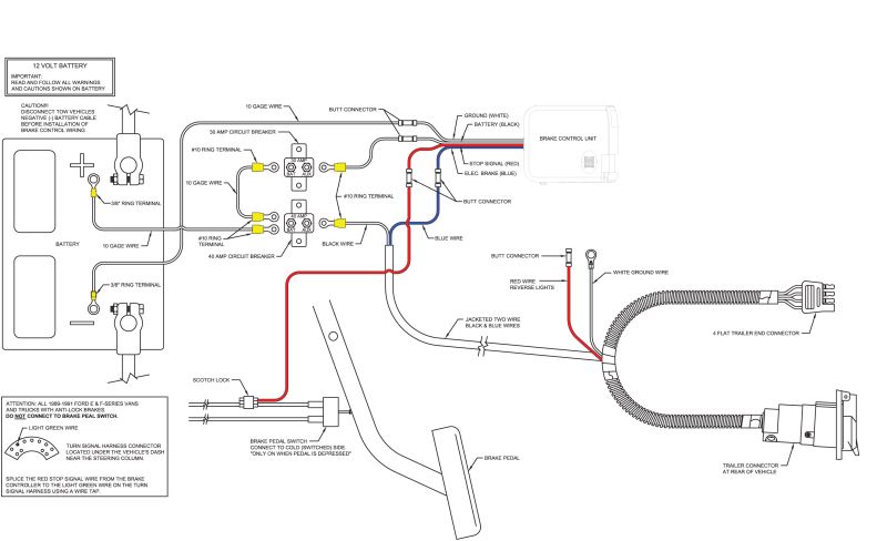
Reese pilot brake controller wiring diagram. Pilot brake electronic brake controller time delayed wiring instructions for pilot trailer brake control part what can cause troubleshooting a reese pilot brake controller that says its connected all the time. Brake controller wiring on a 2002 ford f 250. Large easy to read dual digital display shows properly wired control voltage output to brakes and connection to trailer. Reese towpower pilot brake controller has flexible mounting options with a microprocessor that allows you the ability to read the display even when the controller is mounted upside down. Reese trailer brake controller wiring diagram hayman reese trailer brake controller wiring diagram reese electric brake controller wiring diagram reese pilot trailer brake controller wiring diagram people understand that trailer is a vehicle comprised of quite complicated mechanics. Reese trailer brake controller wiring diagram hayman reese trailer brake controller wiring diagram reese electric brake controller wiring diagram reese pilot trailer brake controller wiring diagram people today comprehend that trailer is a vehicle comprised of very complicated mechanisms.
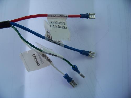
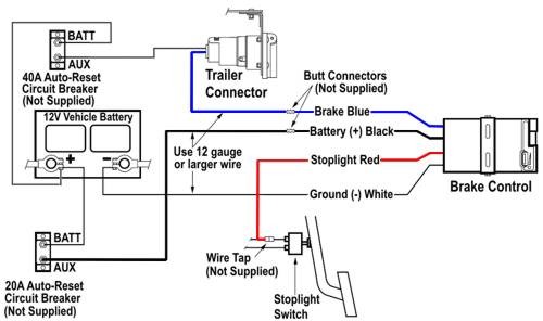
The blue wire carries the brake controller output voltage the white wire provides the ground connection and is usually ran to the negative battery terminal the black wire is the 12 volt power supply and the red wire typically connects to the brake stoplight switch located above the brake pedal. Brake controller wiring colors for gm vehicles. No power out on the blue wire when activating the pilot brake controller on a 1994 ford f 150. This car is designed not just to travel one location to another but also to carry heavy loads. How to wire a 1990 ford f 150 for a brake controller. Locate the slide knob and power knob items a and b in the linked instructions diagram.


