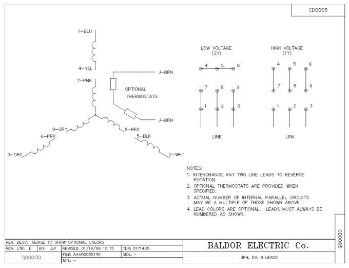
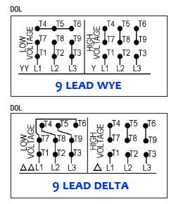
These tips can be used on most electric motor brands such as weg baldor. Refer to mn408 for additional details on lead marking.
Baldor Motor Wiring Diagrams 3 Phase Wiring Diagram
Baldor 3 phase motor wiring. Single phase motor wiring diagram with capacitor baldor single phase motor wiring diagram with capacitor single phase fan motor wiring diagram with capacitor single phase motor connection diagram with capacitor every electrical arrangement is made up of various unique pieces. For example use a red wire nut to connect two 12 gauge wires. Step 5 wire the motor by following the connection diagram. Hold the bare ends of the conductors together and twist on a wire nut. Collection of baldor single phase motor wiring diagram. How to wire a 3 phase motor by michael logan updated july 17.
We offer an extensive line of general purpose single phase enclosed motors. In this video jamie shows you how to read a wiring diagram and the basics of hooking up an electric air compressor motor. Wiring a baldor motor can at first glance look to be a very intimidating task. Standard foot mounted configurations are available as well as c face foot mounted and c face. If this motor is installed as part of a motor control drive system connect and protect the motor according to the control manufacturers diagrams. Baldor motor wiring diagram baldor 5hp motor wiring diagram baldor brake motor wiring diagram baldor dc motor wiring diagram every electrical structure is composed of various diverse parts.
View in online catalog. Refer to the installation manual as necessary as it has a section entitled connection diagrams ensure you follow the guidelines carefully. Yet with the help of this step by step guide this task will be become as easy as counting to five. Each component ought to be placed and linked to different parts in particular manner. Powerwise ink pumps wiring a us motor high voltagewmv duration. Each component should be set and connected with different parts in particular way.
The wiring diagram may also be printed on the box. Cap it with a wire nut. If not the arrangement will not function as it should be. A wiring diagram is a streamlined traditional photographic depiction of an electrical circuit. It shows the elements of the circuit as streamlined shapes as well as the power and signal links in between the tools. Wiring connect the motor as shown in the connection diagrams.
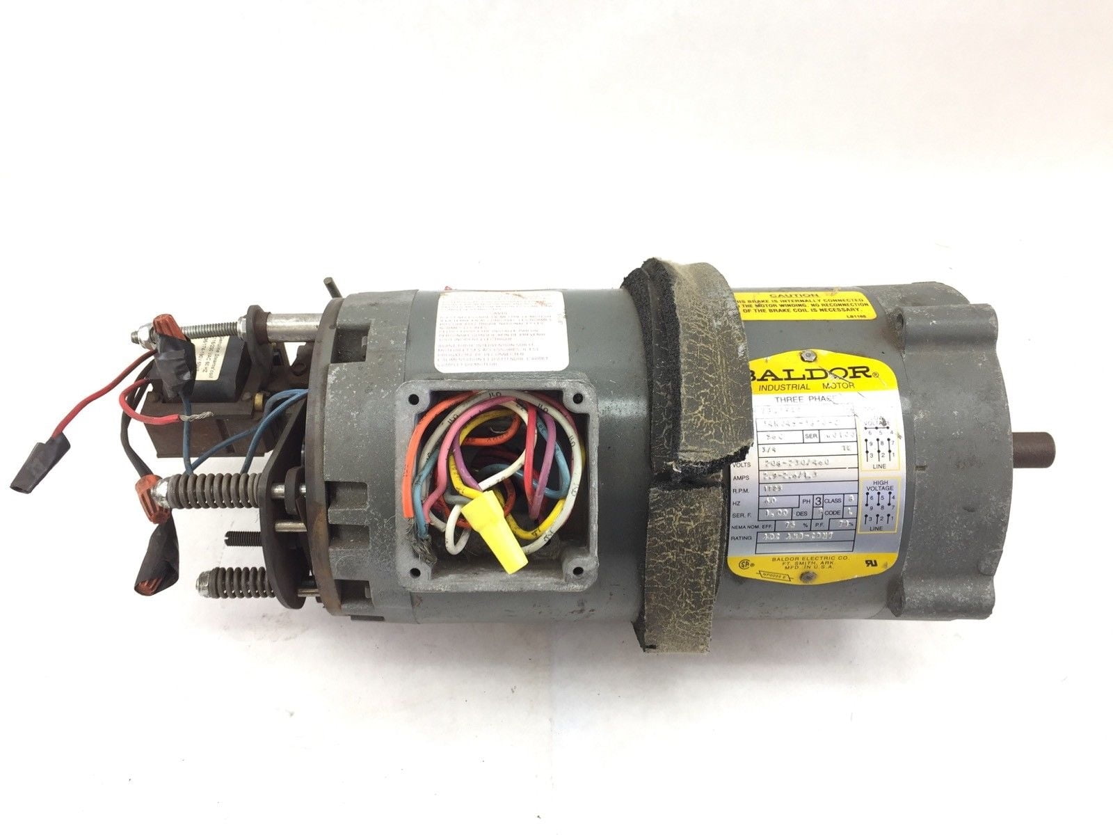
Now for the purposes of safety the steps listed below will only demonstrate how to wire a motor for 240v. Connect a 3 phase baldor reliance motor duration. The wiring fusing and grounding must comply with the national electrical code. Check the wiring diagram located on the name plate on your baldor electric motor. If there is a neutral wire in the conduit or cable supplying the motor it is unused for the motors three phase wiring. In applications where only single phase power is utilized these motors are available from 112 hp through 15 hp in tefc designs.


