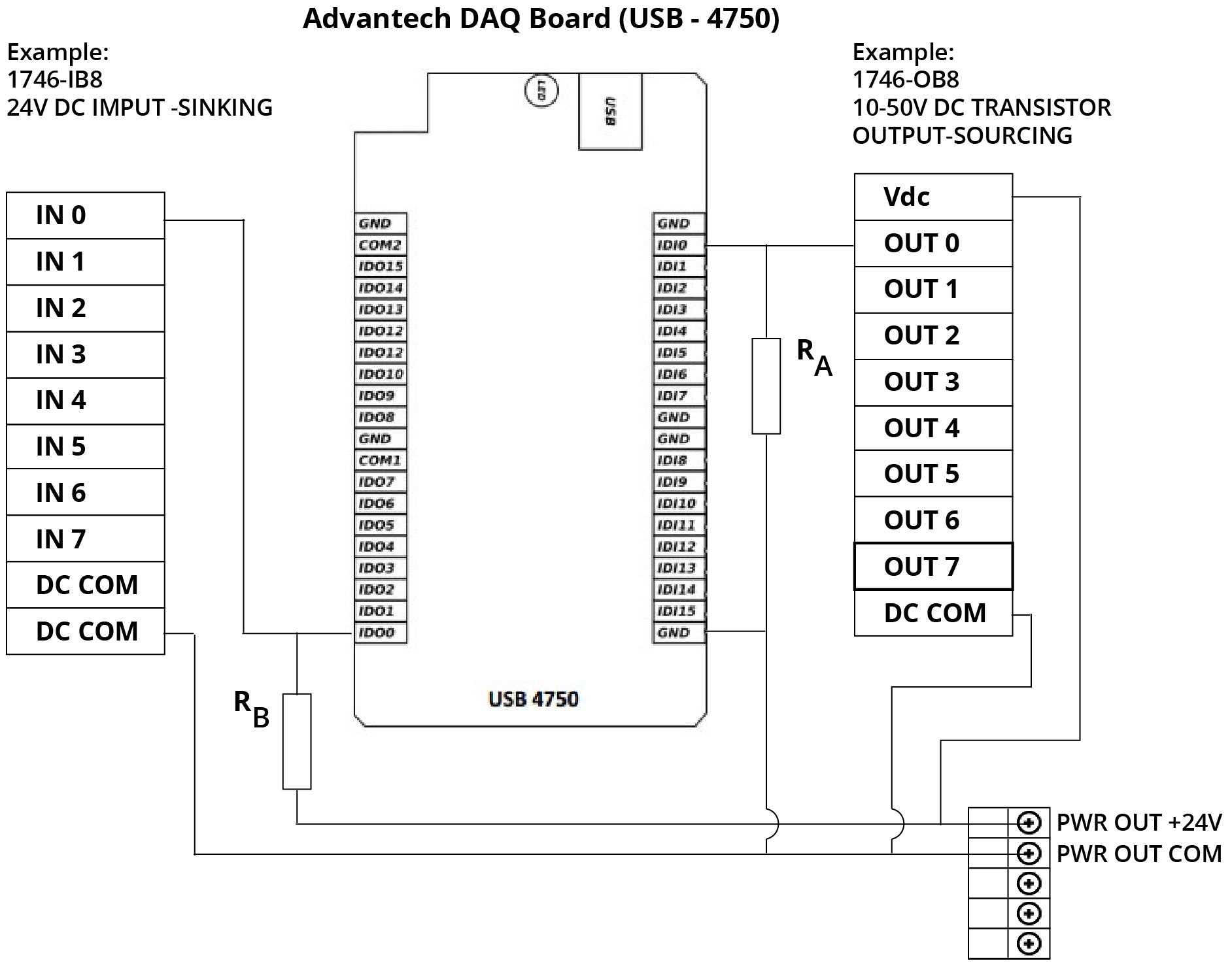
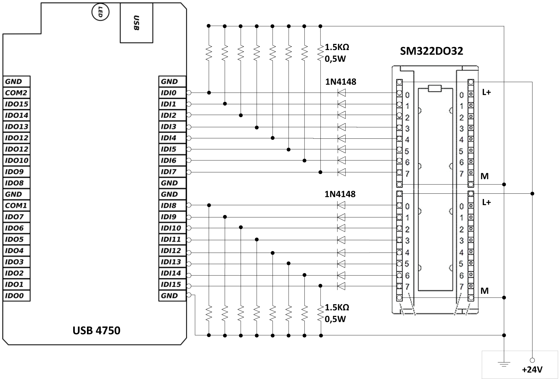
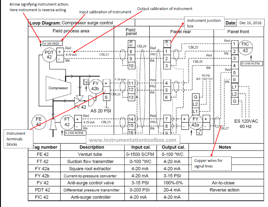
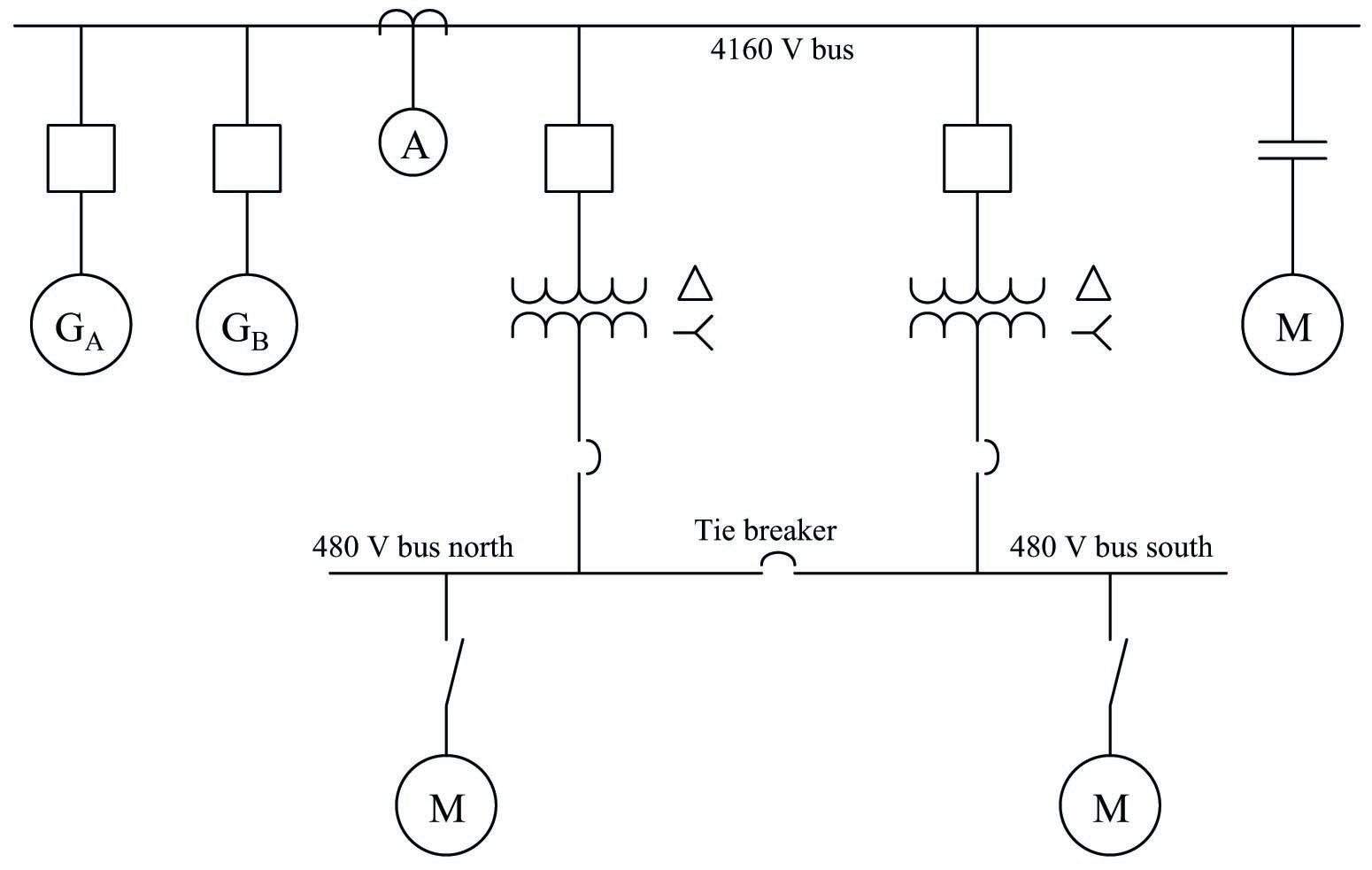
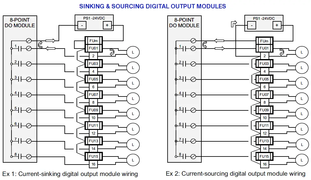
It shows the elements of the circuit as streamlined shapes as well as the power as well as signal connections in between the tools. A wiring diagram is a simplified conventional photographic representation of an electric circuit.

How To Read Control Panel Wiring Diagrams
Plc panel wiring diagram pdf. It is a 2 door control panel on the front of which we have some switches that are connected to the plc inputs and outputs. Assemble the components of the circuit shown in figure 12 on the control board and make the required wiring and connections. Basics 8 aov elementary block diagram. Control panel a panel on which devices such as electromagnetic contactors relays and plcs for controlling machine. As ive mentioned in the previous articles this is a control panel that is used for a system that turns wastewater into clean water. Basics 9 416 kv pump schematic.
A wiring diagram is a simplified conventional pictorial representation of an electric circuit. Basics 13 valve limit switch legend. When including a plc in the ladder diagram still remains. Assortment of plc control panel wiring diagram pdf. A diagram that represents the elements of a system using abstract graphic drawings or realistic pictures. Lets go back and have a look at the control panel and try and figure out some of the connections by following a wiring diagram.
It reveals the components of the circuit as streamlined shapes and the power and also signal connections in between the tools. Variety of plc control panel wiring diagram pdf. Variety of plc panel wiring diagram pdf. Basics 11 mov schematic with block included basics 12 12 208 vac panel diagram. It reveals the elements of the circuit as streamlined shapes and also the power and also signal links between the gadgets. A diagram that uses lines to represent the wires and symbols to represent components.
A fieldbus is a system for serial data transfer in the field area ie. But it does tend to become more complex. Basics 14 aov schematic with block included basics 15 wiring or connection. Basics 7 416 kv 3 line diagram. The installation sensoractuator and controller level. It shows the elements of the circuit as streamlined forms as well as the power as well as signal connections in between the tools.
A wiring diagram is a streamlined conventional pictorial depiction of an electrical circuit. Operation panel a panel on which devices operated by personnel pushbutton switches selector switches etc and devices for notifying personnel of machine states lamps digital displays etc are installed. Plc control panel wiring diagram pdf. Electrician circuit drawings and wiring diagrams youth explore trades skills 3 pictorial diagram. Assortment of plc panel wiring diagram pdf. This figure shows the e stop wired to cutoff power to all of the devices in the circuit including the plc.
A wiring diagram is a streamlined traditional pictorial representation of an electric circuit. Figure 5 below shows a schematic diagram for a plc based motor control system similar to the previous motor control example. Basics 10 480 v pump schematic.


