1 phase size 00 to 3 43 2 phase and 3 phase size 00 to 5 44. 1 cm and 5mm thick mdf board 2.

Nh 7474 Switch Wiring Diagram Rotary Switch Wiring Diagram
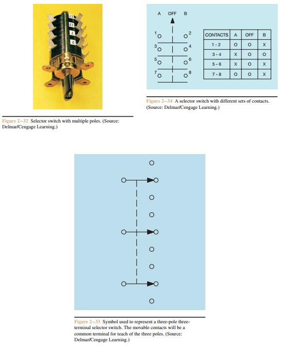
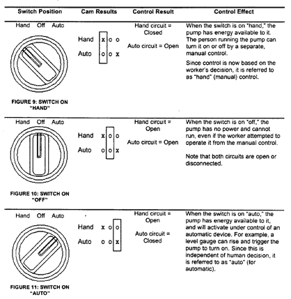
Phase selector switch wiring diagram. 63 amp 4 pole changeover switch on load type 3 its lt make model number was not mentioned anywhere 3. Voltmeter selector switch wiring diagram for 3 phase the wiring connection and voltmeter selector switch wiring diagram is too simple and the connection is same as we do for ammeter selector switch same we connect the l1 l2 and l3 supply connection to rst. In the selector switch connect the all ct coils connection to rst. Choose one of the pickups and unsolder the two pickup wires where they connect to your guitar. 0 230 v digital voltmeter 1 5. A toggle switch for switching on off the voltmeter 1 5.
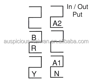
The wiring is fairly simple. In fig 2 different connection and wiring diagrams are shown for a two pole single phase manual changeover switch. Following materials were used. Solder the two jumper wires on the phase reverse switch as shown in the diagram. The upper portion of the changeover switch is directly connected to the main power supply while the lower first and right connections slots are connected to the backup power supply like generator or inverter. Solder the phase switch out wires hot and ground to the exact spots where the pickup wires were before.
In the above diagram i shown the three phase four wire supply with three ct coils. And get supply from a1 and a2 for ammeter. 2 position selector switch 3 position selector. Phase indicator lamps ryb 3 6. To read a wiring diagram first you need to know exactly what basic components are included in a wiring diagram and also which pictorial icons are used to represent them. And get connection for a1 and a2 to voltmeter as shown in above voltmeter selector.
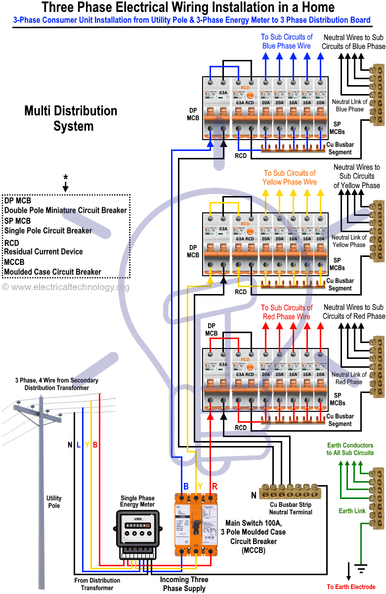
The usual aspects in a wiring diagram are ground power supply cord and link outcome devices switches resistors reasoning entrance lights etc. 63 amp rated 3 terminal connectors 2 4. Wiring diagram book a1 15 b1 b2 16 18 b3 a2 b1 b3 15 supply voltage 16 18 l m h 2 levels b2 l1 f u 1 460 v f u 2 l2 l3 gnd h1 h3 h2 h4 f u 3 x1a f u 4 f u 5 x2a r power on optional x1 x2115 v 230 v h1 h3 h2 h4 optional connection. 720 copper wire a few meters 7.


