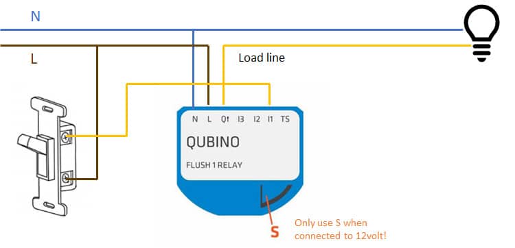
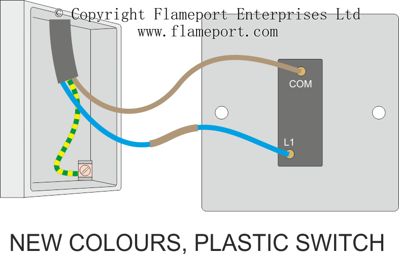
We used an existing switch in an existing junction box. This light switch wiring diagram page will help you to master one of the most basic do it yourself projects around your house.

Home Motion Light Switch Light Wiring Diagram Wiring Diagram
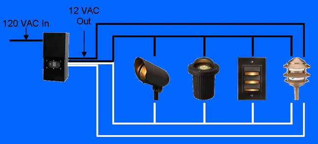
Outdoor light switch wiring diagram. Depending on the model and sensitivity of the motion sensor even a small animal will activate the light switch. Installing a motion sensor to an existing fixture will take approximately an hour of time if you have the proper parts and a few hand tools. Variety of motion sensor light wiring diagram. Your system must have a switch that can turn off the power to the sensor and light fixtures. One at the top and 2 at the bottom. Wiring for outside fixture wiring.
Turn the light switch off first to make sure the lights do in fact turn off to isolate the problem to the wiring at the photocell or the photocell itself. Looking on my switch ive got 3 wire slots per switch. The light switch should always remain in the on position for the photocell to operate automatically. In this video you will see how to wire pir sensor light in the ukit will also show you internal wiring of pir sensor and light. If the lights remain on with the switch off highly doubtful you have something messed up. The ones are the top are labeled common and the bottom ones are way 1 way 2.
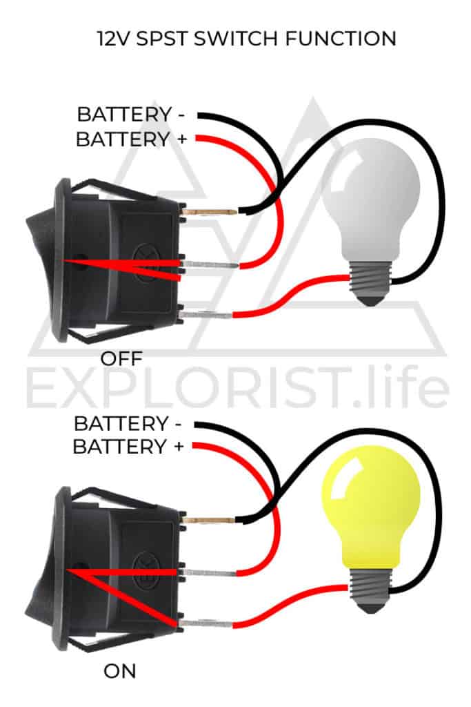
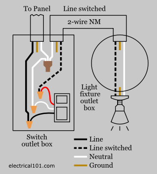
It reveals the elements of the circuit as streamlined shapes and also the power and also signal connections between the tools. The hot and neutral terminals on each fixture are spliced with a pigtail to the circuit wires which then continue on to the next light. If you have a single light just eliminate the wiring that feeds the second fixture. A one way light switch is quite easy to wire up. Both illustrations include additional light fixtures. Wiring a single pole light switch.
This site is merely. Motion sensors automatically control outdoor lights. One outside light on two switches three inside on one switch one on out side switch. You may need to add a box and switch. The cable going to the light switch is connected as follows fig 2. Multiple light wiring diagram.
A wiring diagram is a simplified conventional pictorial depiction of an electrical circuit. Line diagram of a one way lighting circuit using in line method fig 1. Lighting for the home lighting electrical codes light switch wiring electric panel house wiring circuits and circuit breakers. The following will assist you with your electrical question. Hey doing it yourself is great but if you are unsure of the advice given or the methods in which to job is done dont do it. This diagram illustrates wiring for one switch to control 2 or more lights.
The source is at sw1 and 2 wire cable runs from there to the fixtures. More electrical tips and diagrams wwwaboutelectricitycouk like. Ive got the usual wires to go in one light is earthed and the other isnt earth live neutral. The red wire from the feed cable is connected to the top terminal the red wire going to the light is connected to the bottom terminal the.


