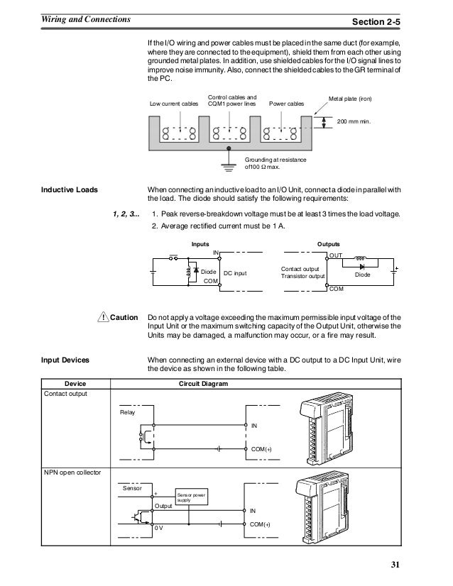
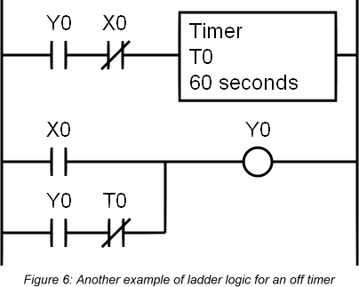
Figure 5 below shows a schematic diagram for a plc based motor control system similar to the previous motor control example. 10 pin alcatel e801 cell phone proprietary connector at the plc.
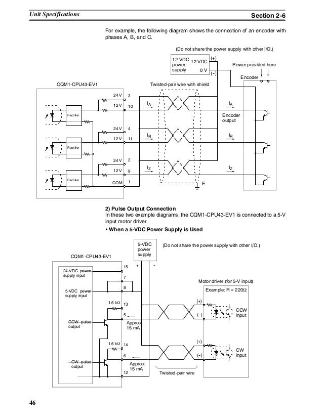
Omron Plc Cqm1 Opearation Manual
Omron plc wiring diagram. Terminals are available for both inputs and outputs. Io relay terminals io relay terminals simplify connecting plcs and other controllers and help reduce wiring in control panels. A wiring diagram is a simplified conventional photographic representation of an electric circuit. The diagram also. It shows the elements of the circuit as streamlined shapes as well as the power as well as signal connections in between the tools. Achieve wiring with one connecting cable.
Pinout of omron plc to rs 232 calbeomron plcs periherial connector to pc rs 232 cable offical cable names. Omron plc e learning lesson introduction to plc this video explains about omron plc wiring fundamentals sink source principle plc static inputoutput check program downloadupload procedure. Variety of omron plc programming cable wiring diagram. Omron provides general purpose relays io relays power relays latching relays and ratchet relays. It shows the elements of the circuit as streamlined forms and also the power and signal links in between the devices. Cqm1 cif02 or cs1w cn226 pinouts devices connectors.
Io relay terminals simplify connecting plcs and other controllers and help reduce wiring in control panels. A wiring diagram is a simplified conventional pictorial depiction of an electrical circuit. Omron plc to rs 232 calbe pinout. For control panel for built in. Wiring diagram plc omron. Theodore handsmith march 17 2019.
This figure shows the e stop wired to cutoff power to all of the devices in the circuit including the plc. Collection of plc wiring diagram software. A wiring diagram is a streamlined standard photographic representation of an electrical circuit. Pinouts various electronic devices omron pinouts. When including a plc in the ladder diagram still remains. Wiring work is eliminated and installation work is reduced helping to simplify maintenance.
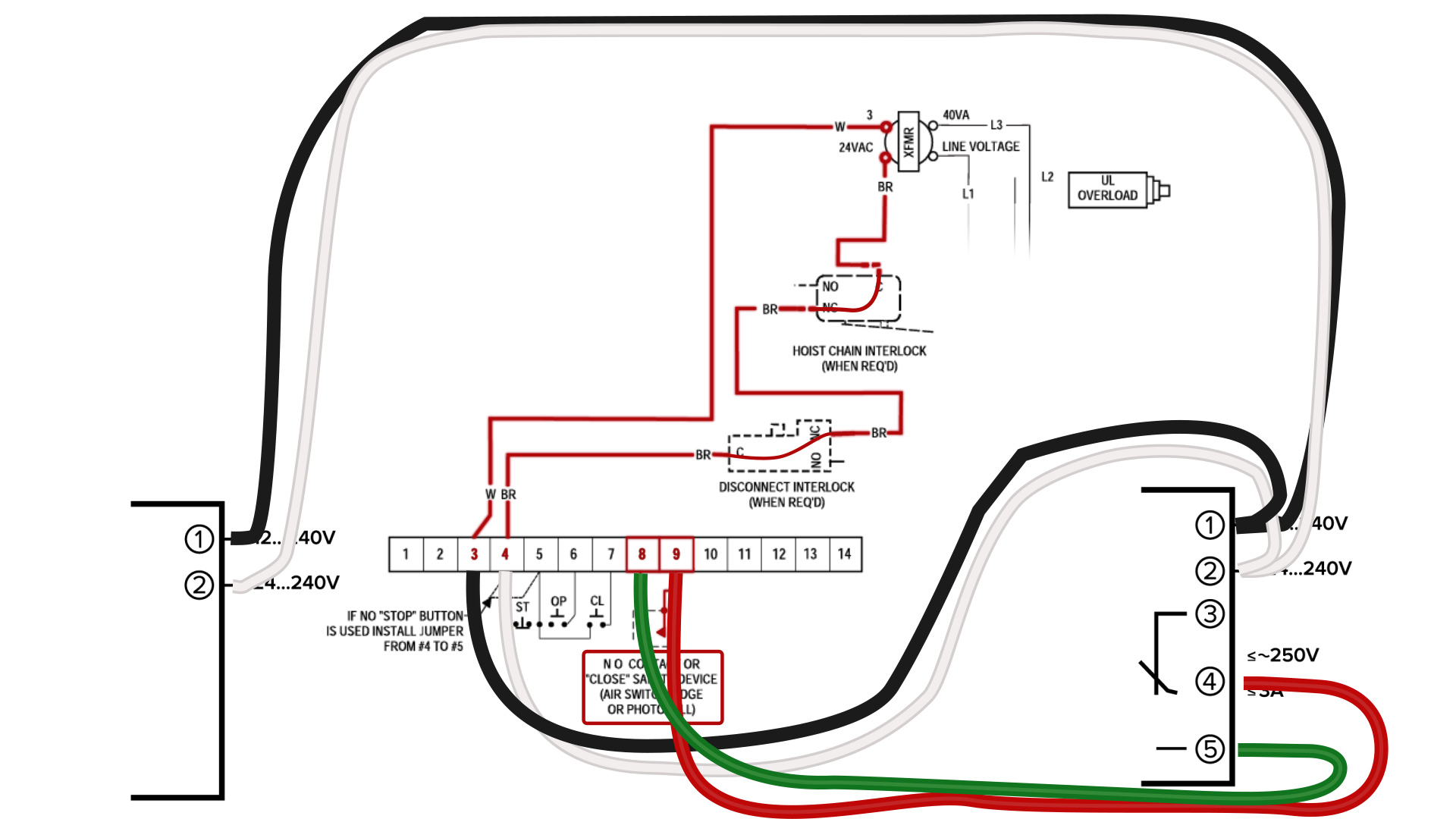
But it does tend to become more complex. Appendices wiring diagrams a 3 1 cpu units cpu unit with 20 io points input wiring diagram output wiring diagram all models relay outputs ac power supply cp1e e20dr a cp1e e20dr a cp1e n20dr cp1e n20d cio 100 cio 0 24v dc com com nc com nc com 06 l1 l2n com 01 100ch dc power supply. Assortment of plc panel wiring diagram pdf. Wiring diagrams show how a wires are connected and where they will need to perfectly located at the authentic device as well as the bodily connections between each one of the components.





.jpg)


