In this lesson well learn to read and interpret motor connection diagrams and determine the electrical relationship of the stator windings using motor connection diagrams. Always use wiring diagram supplied on motor nameplate colored leads are only applicable on the new rolled steel motor lines.
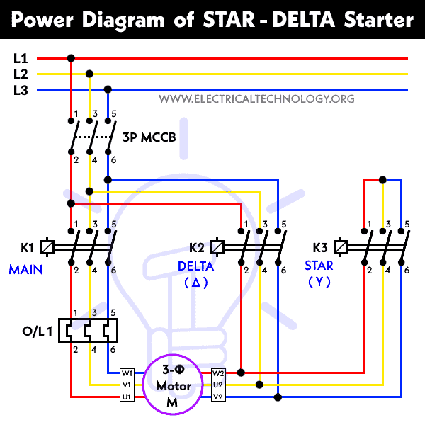
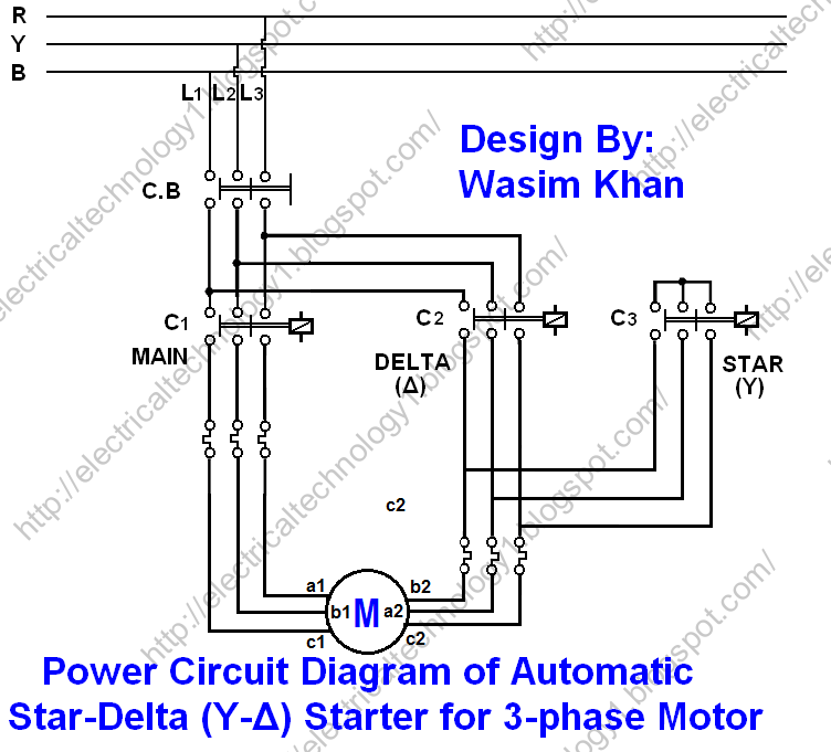
Star Delta Starter Motor Starting Method Power Amp Control Wiring
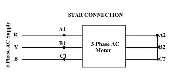
3 phase delta motor connection diagram. A star delta starter is the most commonly used method for the starting of a 3 phase induction motorin star delta starting an induction motor is connected in through a star connection throughout the starting period. Wye delta starter wiring diagram sanelijomiddle wire center. Therefore the motor winding will be connected in delta. The three phase supply shown with red yellow and blue coolers all connection with a 3 phase induction motor. Wye start delta run motor wiring diagram collections of great three phase motor wiring diagram 3 star delta and how to wire. Star delta starter wring for 3 phase motor diagram here i shown the complete star delta starter wiring diagram 3 phase.
Wiring diagram for star delta motor starter best wiring diagram star. Wye delta starter wiring diagram sanelijomiddle wire center. Split phase motor dual voltage reversible rotation capacitor motor single phase wiring diagrams always use wiring diagram supplied on motor nameplate. In addition contact 2 which is in the line c3 will open by which there would not be any chance of activation of coil 3 c3 since the motor is connected in delta now therefore each phase of the motor will receive full line voltage 400v and the motor will start to run in full motion. Line phase current and line phase voltage in delta δ connection. W2 cj2 ui vi wi.
Then once the motor reaches the required speed the motor is connected in through a delta connection. Delta connection in a 3 phase system in delta δ or mesh connection the finished terminal of one winding is connected to start terminal of the other phase and so on which gives a closed circuitthe three line conductors are run from the three junctions of the mesh called line conductors. The diagonal of that parallelogram shows the vector difference of i r and i b which is equal to current in line 1 i 1. The current of line 1 can be found by determining the vector difference between i r and i b and we can do that by increasing the i b vector in reverse so that i r and i b makes a parallelogram.


