The excel based application was designed with a unique workbook structure providing ic engineers with a faster more accurate way to produce instrument junction box and iom drawings. The national electrical code nec dictates that no wiring splices are allowed outside of an approved enclosure.

Troubleshooting Fieldbus Devices Electrical Wiring Diagram
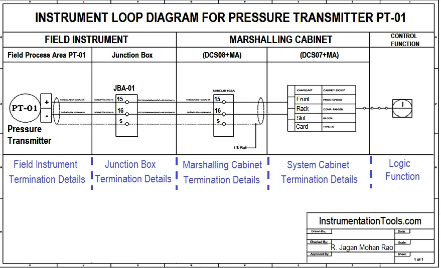
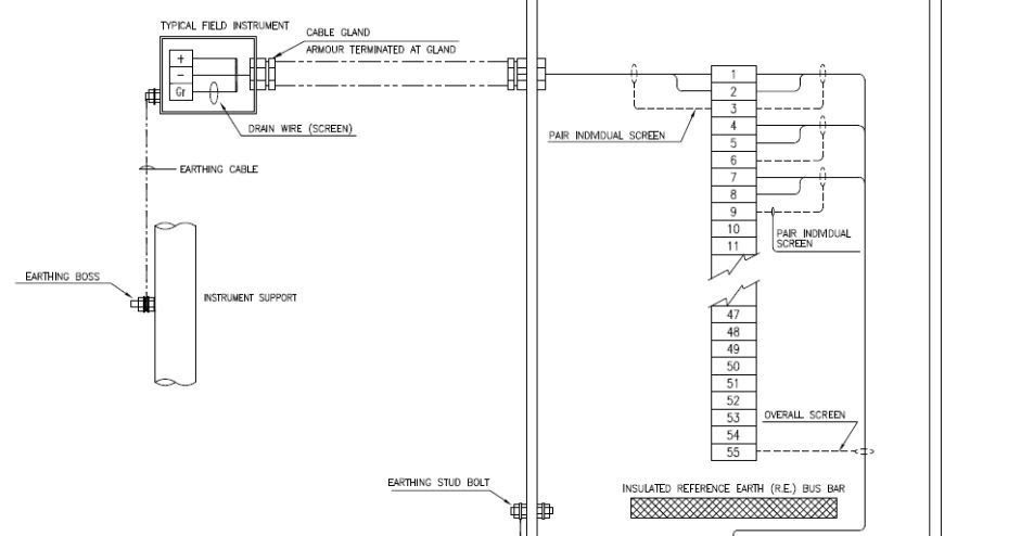
Instrument junction box wiring diagram. Every instrument in a loop drawing has an input calibration and an output calibration specified for the instrument. Wiring harnesses are joined by using a multiple plug and receptacle connector block or a terminal post chassis junction block. Or field me lage junction box tak main cable ke through phuchti hai or fir junction box se field me lage sov tak. Any standard outlet switch box or light fixture box can serve as an approved enclosure but where a wiring splice needs to occur in other locations along the circuit the approved enclosure is usually a junction boxa junction box is simply a standard electrical box that is. Plc connection between instrument junction box marshalling system cabinet a plc connection represents the signal flow starting from the field transmitters junction box marshalling cabinet system cabinet and human machine interface for the operator graphic display. Conventional junction box convectional junction box contains terminal strip and earth stripearth bus bar only.
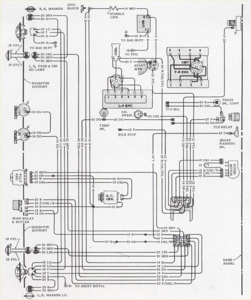
Each harness or wire must be held securely in place by clips or other holding devices to prevent chafing of. In the instrument panel area plastic insulated blade type connectors and screw type terminals are used. 73 76 firewall junction 73 76 instrument cluster 77 80 77 80 250 i6 engine wiring and front lighting 77 80 292 i6 and bbc engine wiring 77 80 sbc engine wiring 77 80 cab interior 77 80 chassis and rear lighting 77 80 intrument panel page 1 77 80 intrument panel page 2 81 87 81 87 cab interior page 1 81 87 cab interior page 2 81 87 chassis and. Cable numbers wire colours junction block numbers panel identification and grounding points are all shown in loop diagrams. Junction box wiring diagram connecting cables using a junction box. This application has an instrument database where data is logically entered and used in many different ways for configuring plant automation strategies.
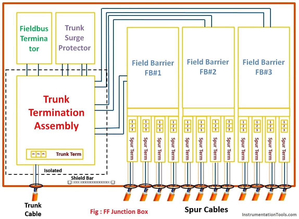
Creating a spur using a junction box. Instruments field pair core cable from instruments to junction box for transmitters switches valves solenoid valve etc is. Digital output sov wiring diagram from dcs card to field sov instrument guru. If you want to spur off from a current circuit to provide power to a new socket of light again make sure the power is off and the circuit is isolated and wire your junction box using the method below. How will a field jb of conventional 4 20ma connection look different from that of ff jb.

