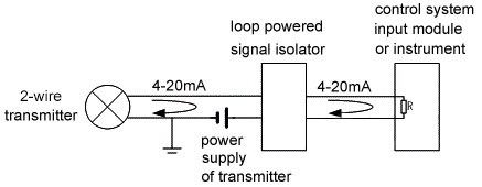
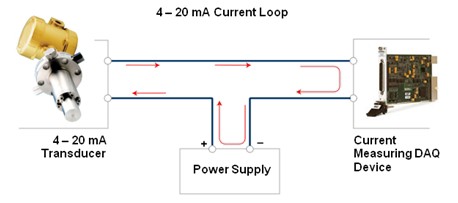
Wiring diagram of loop powered isolator with input signal of 2 wire transmitter. What is electrical wiringdifferent types of electrical wiring systems.
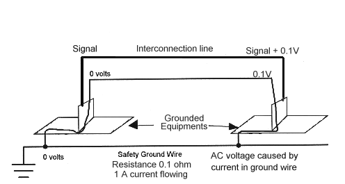
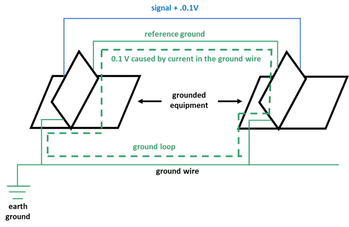
Ground Loop Basics
Loop in wiring system diagram. This section will focus on the standard. Instead we use a switch loop wiring pattern to control when you want the light on and off. Connection with purchasers use of any of the products listed herein or for any section 2. Loop in or looping systemcasing and capping wiringbatten wiring cts or trslead sheathed wiringconduit wiringsurface conduit wiringconcealed conduit wiringtypes of conduitmetallic conduitnon metallic conduit. The advantages of the loop in method is all the connections are accessible and can easily be inspected and maintained as per the current electrical regulations. This page contains wiring diagrams for household light switches and includes.
Joint box or tee or jointing system. How does electrical switch wiring work. If you simply connected the wires from the light to the switch the light would always be on. A switch loop single pole switches light dimmer and a few choices for wiring a outlet switch combo device. Loop in lighting wiring is the modern cabling arrangements used in most installation. This method will work with the control systems offered in most two rail track train sets on the market today.
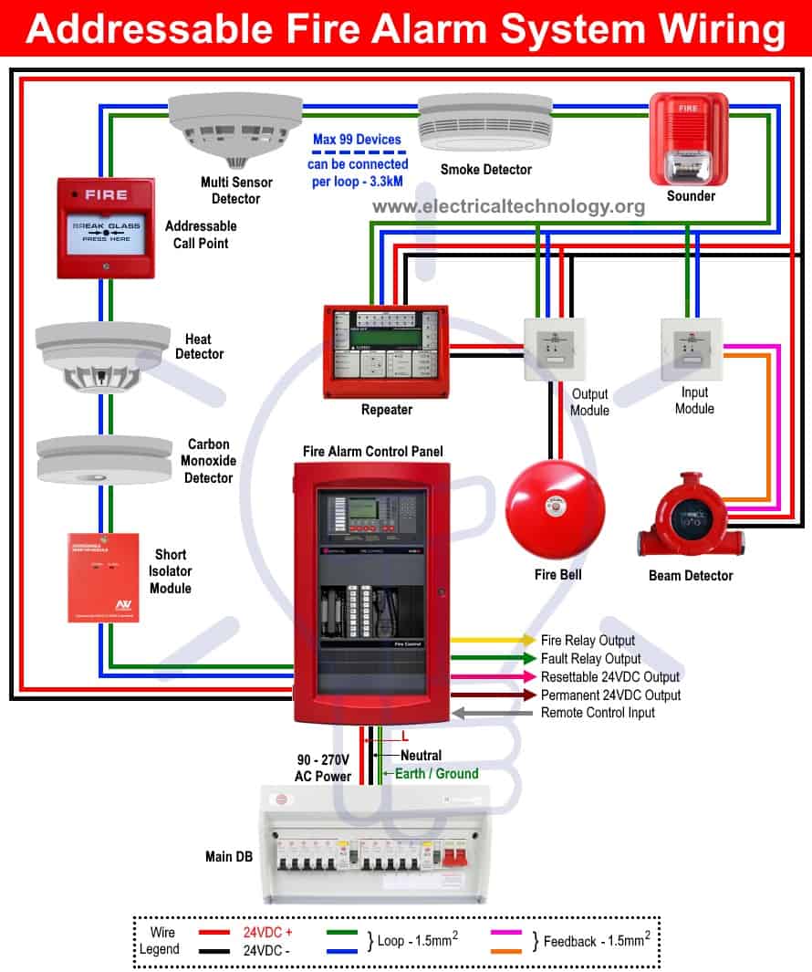
Line diagram of a one way lighting circuit using loop in. Since the power supply provided by the power distribution function of the control system input module or input of instrument is not isolated from the input terminal the output signal of the power supply mode of the transmitter is common grounded with power. Loop drawings can be customized per customer taste although certain minimum standard information is required to be included in loop sheets. Wiring a reverse loop for dc operation if your model railroad uses a conventional dc direct current power supply adding a reverse loop is only a toggle switch away. Fire alarm system requirements system overview. Also included are wiring arrangements for multiple light fixtures controlled by one switch two switches on one box and a split receptacle controlled by two.
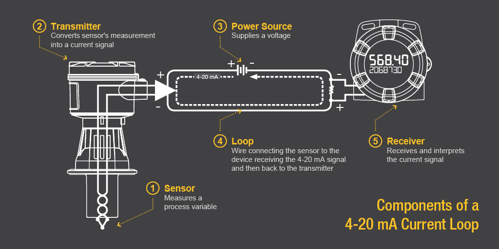
Cleat wiring methods of electrical wiring systems wrt taking connection. Loop diagram will detail the connections of pneumatics and wiring from the field device through any junction boxes or marshalling cabinet to the controller or computer interface which controls the process a single loop or a cascade loop of the process. However the more detail you put into a loop diagram the easier it makes the inevitable job of maintaining that system at some later date. Modern ceiling roses are designed to facilitate this method of wiring. In a switch loop the hot and neutral wires arrive at the light fixture before reaching the switch. One way lighting circuit using loop in ceiling roses.
Generally it uses less materials and is quicker to install than radial junction box wiring it can however be a bit more complicated to work out the actual wires at a ceiling rose. Analogue addressable smoke detector with remote led. Installation wiring diagram control panel system installation manual.

