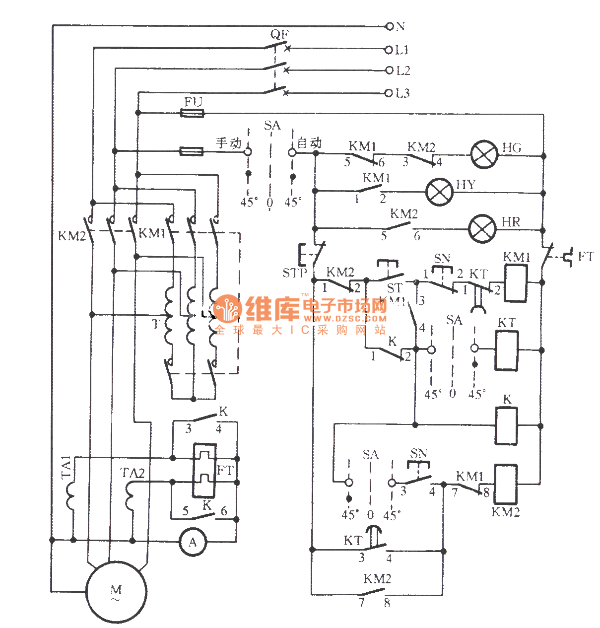
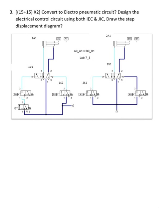
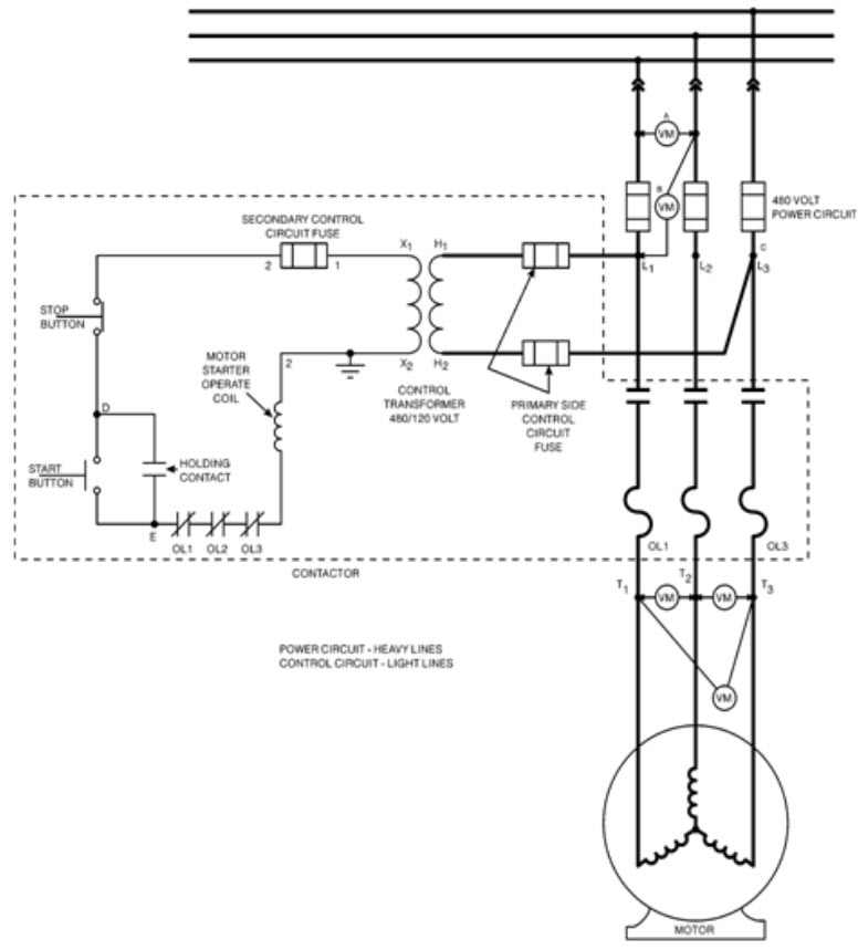
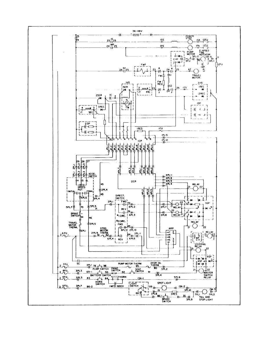
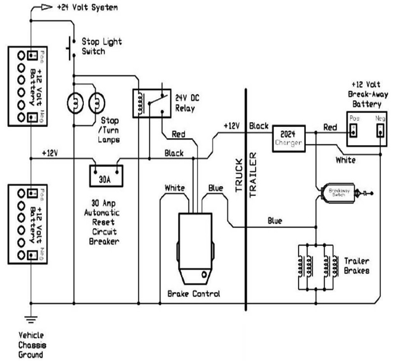
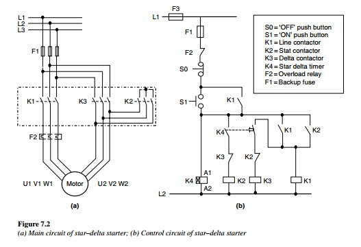
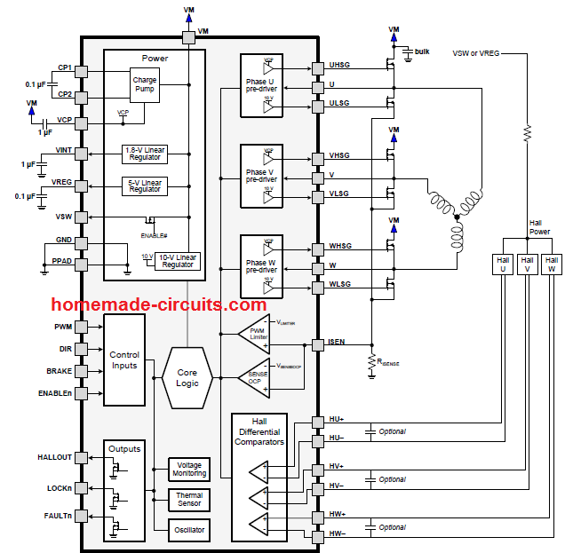
A wiring diagram is used to represent how the circuit generally appears. An electric circuit is a closed loop with a continuous flow of electric current from the power supply to the load.

Asd
Electrical control circuit diagram. A wiring diagram is a simple visual representation of the physical connections and physical layout of an electrical system or circuit. Electric circuits like ac lighting circuit battery charging circuit energy meter switch circuit air conditioning circuit thermocouple circuit dc lighting circuit multimeter circuit current transformer. It shows how the electrical wires are interconnected and can also show where fixtures and components may be connected to the system. Also explain the operation of this motor control circuit. Based on your observations of these two diagrams explain how electromechanical relays are represented differently between ladder and schematic diagrams. Three phase motor power control wiring diagrams 3 phase motor power control wiring diagrams three phase motor connection schematic power and control breaking news up tp 93 off launching official electrical technology store shop now.
To help illustrate the differences between wiring diagrams and schematics a basic control circuit will first be explained as a schematic and then shown as a wiring diagram. Wiring diagrams show components mounted in their general location with connecting wires. Feb 5 2020 explore elects agass board electrical diagram on pinterest. See more ideas about electrical diagram electrical circuit diagram electrical engineering. Interpret this ac motor control circuit diagram explaining the meaning of each symbol. Here are ten simple electric circuits commonly found around the home.


