The stator circuit model of an induction motor consists of a stator phase winding resistance r 1 stator phase winding leakage reactance x 1 as shown in the circuit diagram below. That is when an emf is supplied to its stator then as a result of electromagnetic induction a voltage is induced in its rotor.

Performance Calculation For Double Sided Linear Induction
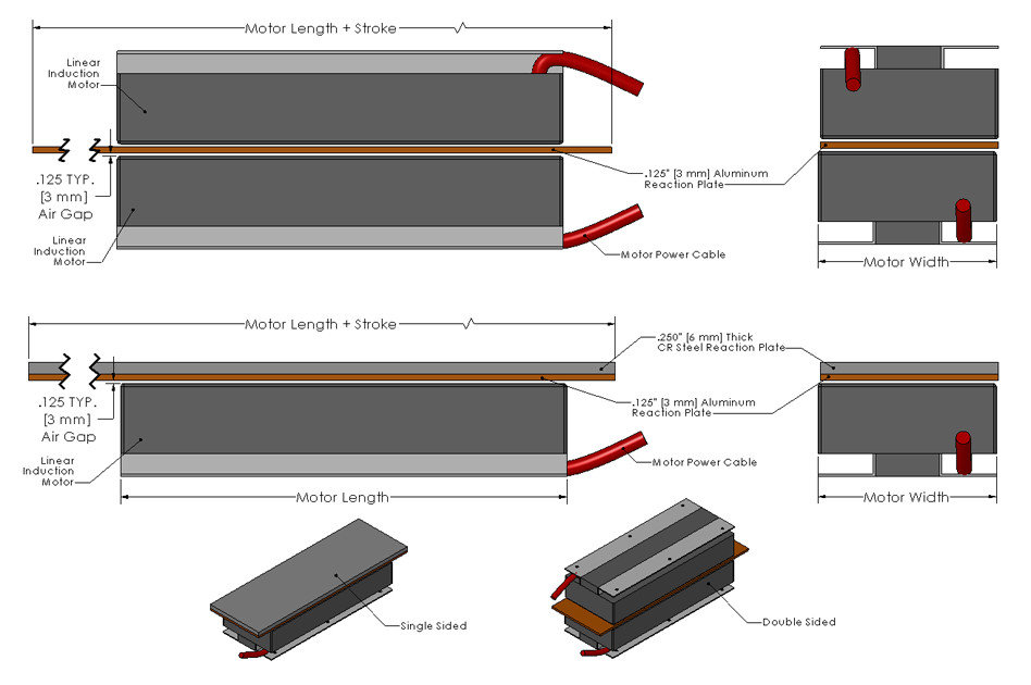
Linear induction motor diagram. To understand the circle diagram of induction motor we should first know what is the circle diagram. In the present paper the mover speed control of a linear induction motor lim using a sliding mode control design is proposed considering the end effects. Linear induction motor a linear induction motor lim is an advanced version of rotary induction motor which gives a linear translational motion instead of the rotational motion. Characteristically linear induction motors have a finite primary or secondary length which generates end effects whereas a conventional induction motor is arranged. Patent 782312 1905 inventor alfred zehden of frankfurt am main for driving trains or lifts. So an induction motor is said to be a transformer with rotating secondary.
The history of linear electric motors can be traced back at least as far as the 1840s to the work of charles wheatstone at kings college in london but wheatstones model was too inefficient to be practical. A linear induction motor lim is a non contacting high speed linear motor that operates on the same principal as a rotary squirrel cage induction motor. In this type of motor the stator and rotor are called primary and secondary respectively. And its based on the approximate equivalent circuit. The no load current i 0 is simulated by a pure inductive reactor x 0 taking the magnetizing component i µ and a noninductive resistor r 0 carrying the core loss. They are capable of speeds up to 1800 insec 45 ms and are typically used in applications where accurate positioning is not required.
Before deepen in steps of drawing the diagram it. Capacitor start capacitor run induction motors are single phase induction motors that have a capacitor in the start winding and in the run winding as shown in figure 12 and 13 wiring diagram. Circle diagram of induction motor. So it is also called the rotating transformer. The circle diagram is a graphic representation of the performance of the machine and its drawn in terms of the locus of the input voltage and current. A feasible linear induction motor is described in the us.
An induction motor is a well known device which works on the principle of transformer. Here primary of transformer resembles stator winding of. The stator is cut axially and spread out flat. A linear induction motor or lim is a special type of induction motor used to achieve rectilinear motion rather than rotational motion as in the case of conventional motors. The bl ock diagram of. Linear induction motors are quite an engineering marvel to convert a general motor for a special purpose with more or less similar working principle thus enhancing its.
This type of motor is designed to provide strong starting torque and strong running for applications such as large water pumps. A linear induction motor lim is an alternating current ac asynchronous linear motor that works by the same general principles as other induction motors but is typically designed to directly produce motion in a straight line.


.svg)


