12 n type plugs are used for road lighting only. This connection is very simple connection and most used in electrical house wiring.

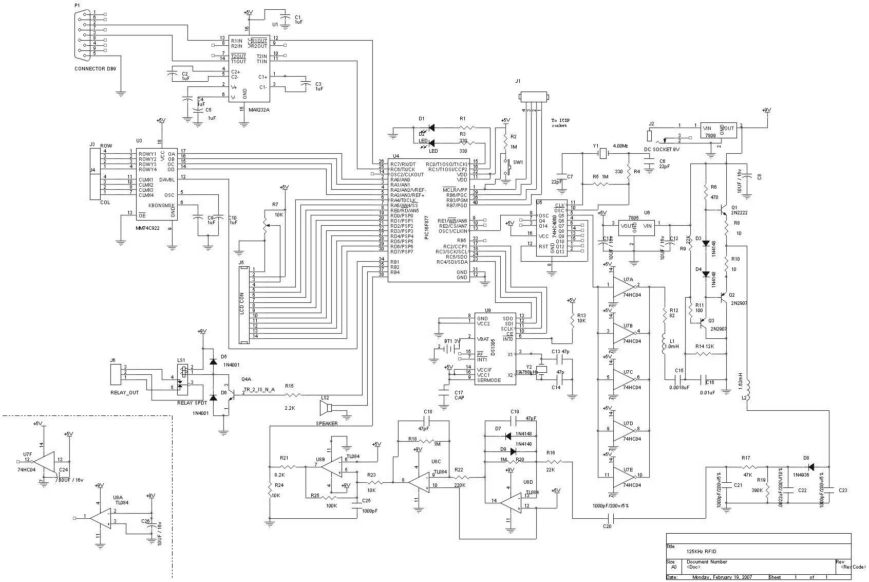
Is This A Correct And Good Wiring Diagram Esk8 Electronics
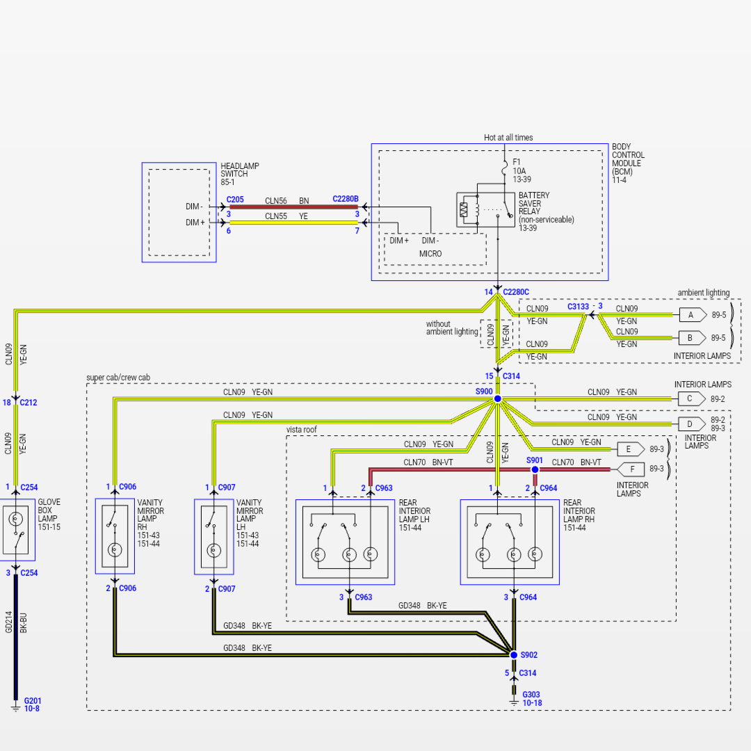
Light board wiring diagram. This is slowly being replaced by the european 13 pin plug and will become less popular as the reverse light is introduced to new trailers between now and 2012 when it will be legal requirement. Day night sensor switch circuit 8. Wiring diagram of single phase distribution board with rcd in nec us iec uk eu electrical wiring color codes double pole mcb dp the isolator or main switch this is the main operating switch which is used to control the electric power supply in the buildings. Multiple light wiring diagram. Automatic day night light. Street light sensor connection 10.
The hot and neutral terminals on each fixture are spliced with a pigtail to the circuit wires which then continue on to the next light. Try making your splice connections at the rear passenger kick panel. Photocell wiring diagram 6. The source is at sw1 and 2 wire cable runs from there to the fixtures. Wiring light switch is first step which learn by a electrician or electrical student. Light switch wiring diagram.
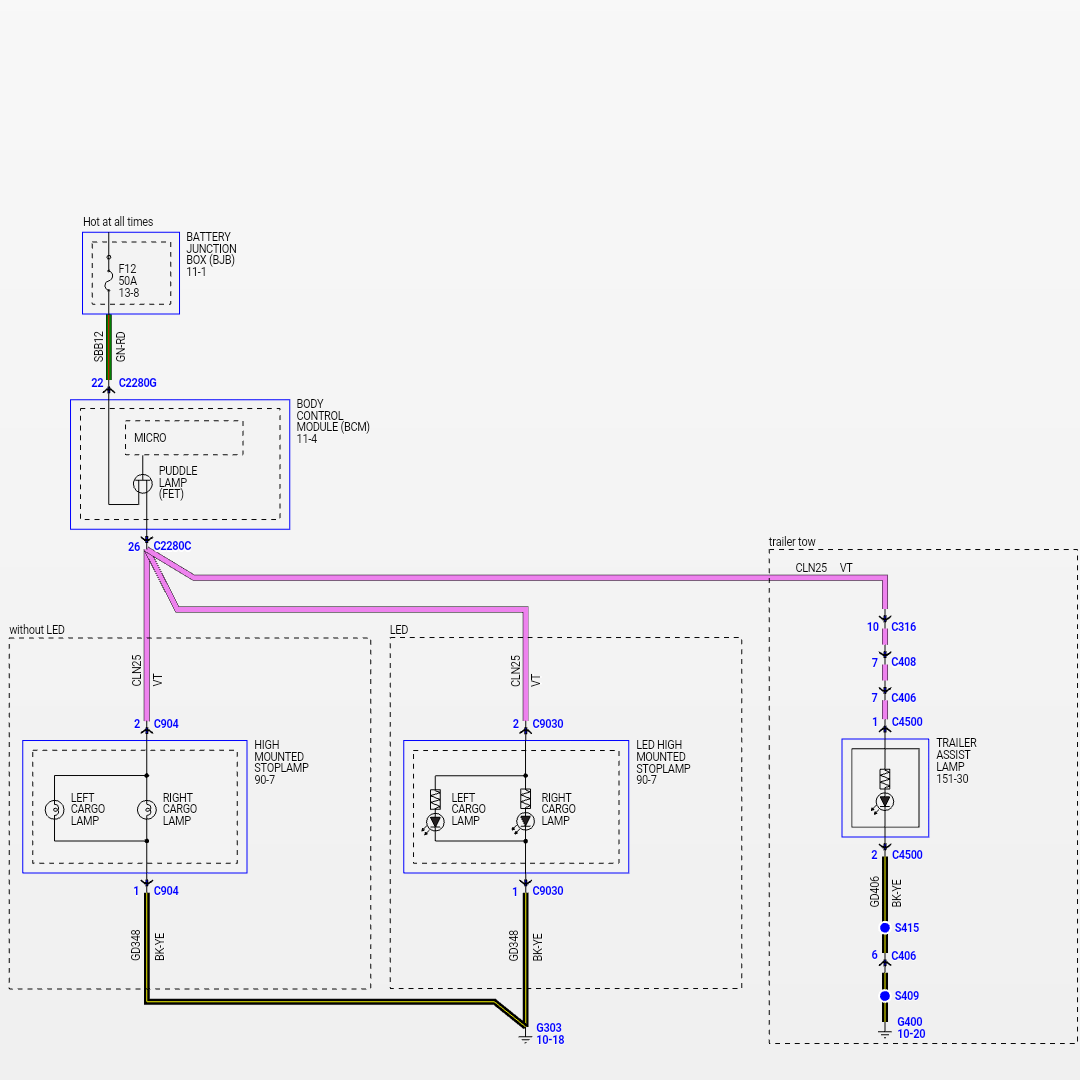
Here are some suggested wiring guides to help you get started. 7 pin 12n wiring diagram. Light sensor switch 9. Photocell wiring diagram with contactor 7. This connection can be done by one way switch a light bulb socket light bulb and electric wires. Wiring up the f150leds running board light is quick and easy.
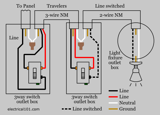
This diagram illustrates wiring for one switch to control 2 or more lights.


