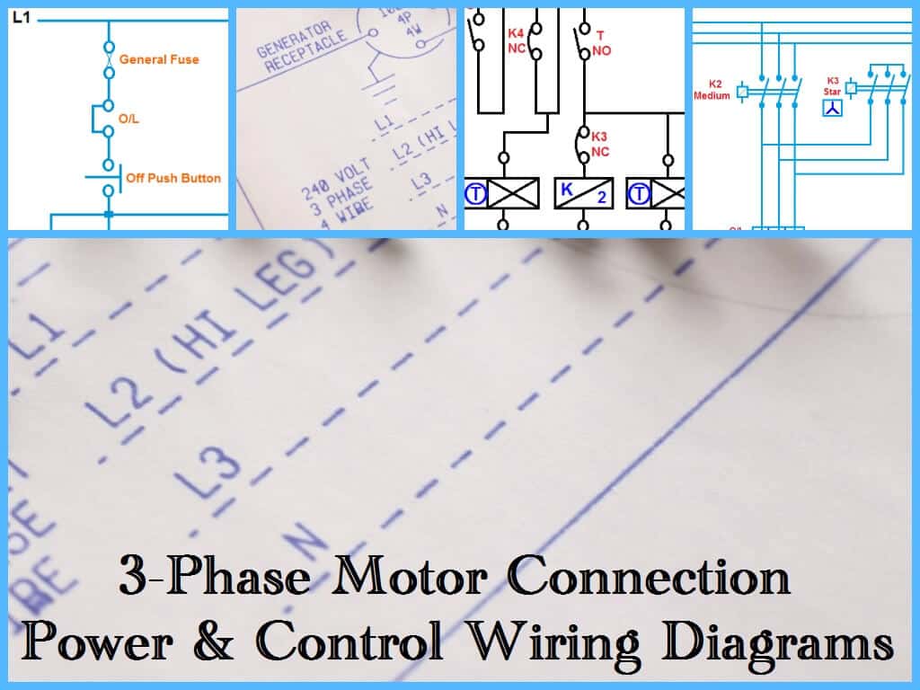
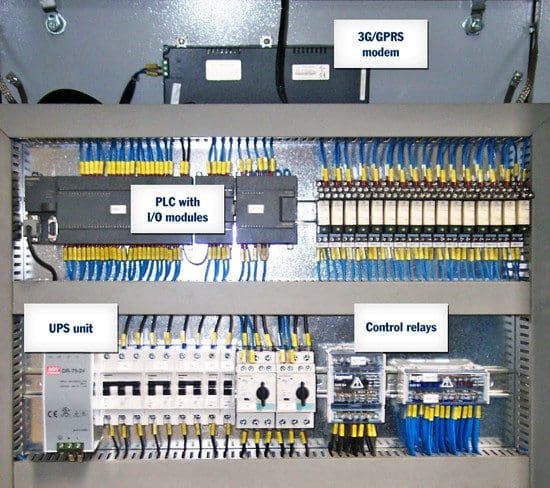
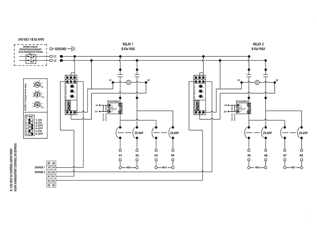
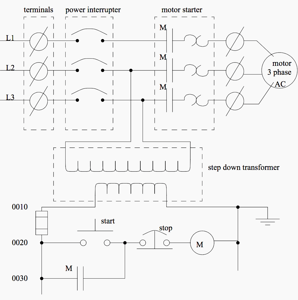
An example of a wiring diagram for a motor controller is shown in figure 1. The lcp100 local control panel has four 4 mounting holes for onsite mounting of the device.

Lcp2 Control Panel Wiring Diagram
Lcp panel wiring diagram. Lcp panel wiring diagram unknown 854 am. A lighting control system is an intelligent network based lighting control solution that incorporates. Lighting control panel using contactor and relay what is a lighting control panel. Refer to the appropriate wiring diagram as defined in table 3 based on your protection method and installation requirements. This system uses 3 phase ac power l1 l2 and l3 connected to the terminals. Note that symbols are discussed in detail later.
Also refer to figure 4 for lcp100 switch setting terminal connections and label details and information as well as dvc6200 sis terminal box details. The three phases are then connected to a power interrupter. Dashed lines indicate a single purchased component. 3 november 2015 lighting control panel wwweatoncomligtingsystems wiring diagram nnoeesample wiring diagram for a lcpa model sample system topology. Lcp u lighting control panel is a rugged nema1 grade panel made of 16 ga steel with a white powder coat finish used to simplify the design and installation of pulseworx dimmers. Lcp128 panel with adaptive dimming module lcp128 panel with adaptive dimming module dimmed elv transformer by others elv transformer by others electronic lowvoltage continued fluorescent 3wire lcp128 spec grade panel lcp128 panel with dimming module 3wire ballast hilume hilume 3d ecosystem 3wire ballast.
The lighting control panel provides ample room to house up to ten ws1dl 24 fifteen ws1dl 15 or twenty ws1dl 6 dimmers controlling a maximum of 20 individual circuits.


