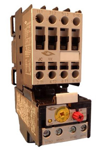
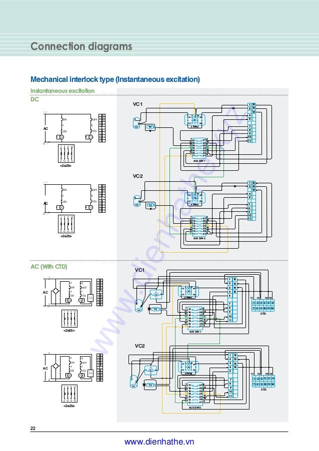
Many large pieces of equipment are powered directly from high voltage lines. Assembly your own direct on line motor starter.
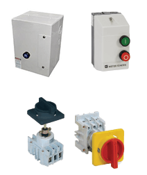
Home Tc Electric Controls
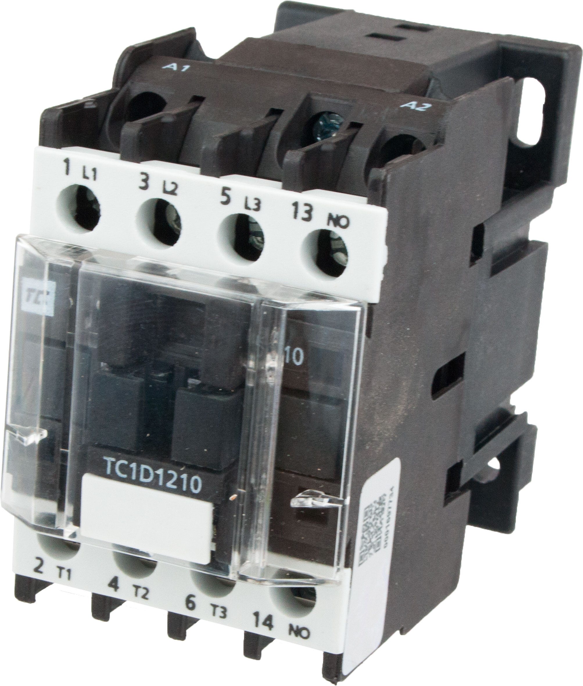
Tc contactor wiring diagram. Basics 11 mov schematic with block included basics 12 12 208 vac panel diagram. Basics 13 valve limit switch legend. Has anybody any wiring advice on a hager 25 amp contactor or a website where i can get a wiring diagram i have never fitted one before but need to friday. Like subscribe and dont skip the ads facebook subscribe our page to. Pixma may 2 2007. 3 phase dol starter control and power wiring diagram.
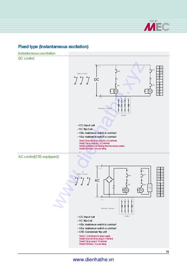
They show diagrams for 240 and 415 vac control. 4 table 2 nema and iec terminal markings. Step by step guide how to wire contactor and motor protection switch. Ryb electrical 88232 views. Its is important to. The most common for small direct on line starters dols is 415vac as this requires no neutral to be fed to the starter.
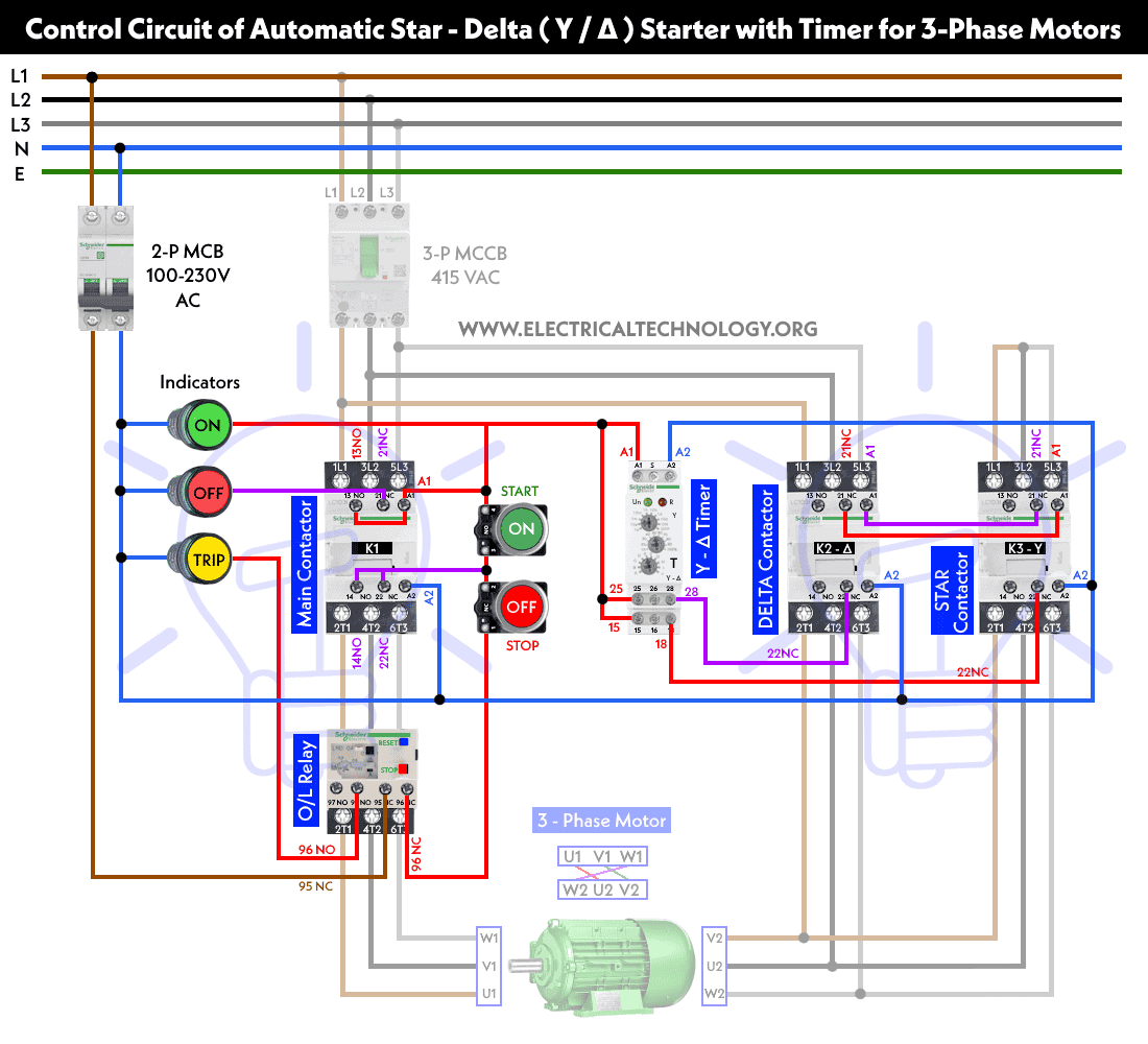
Basics 14 aov schematic with block included basics 15 wiring or connection. Basics 7 416 kv 3 line diagram. Cheers if anybody can help. It shows the elements of the circuit as streamlined shapes as well as the power and signal links in between the tools. Contactor breakers limit switch no static control standard elementary diagram symbols. In this tutorial we will show the star delta y δ 3 phase induction ac motor starting method by automatic star delta starter with timer with schematic power control and wiring diagram as well as how star delta starter works and their applications with advantages and disadvantages.
Basics 10 480 v pump schematic. Contactor wiring and i hope after this post you will be able to wire a 3 phase motor i also published a post about 3 phase motor wiring with magnetic contactor and thermal overload relay but today post and contactor wiring diagram is too simple and easy to learn. How to connect a contactor. Attached is a pdf file with pictorial diagrams 1 of how you would connect the four most common variants of a dol starter. These lines far exceed the 120 volts ac standard in most homes. A wiring diagram is a streamlined traditional photographic depiction of an electrical circuit.
Collection of baldor single phase motor wiring diagram. Water pump controller with float switch duration. Basics 9 416 kv pump schematic. Wiring diagram book a1 15 b1 b2 16 18 b3 a2 b1 b3 15 supply voltage 16 18 l m h 2 levels b2 l1 f u 1 460 v f u 2 l2 l3 gnd h1 h3 h2 h4 f u 3 x1a f u 4 f u 5 x2a r power on optional x1 x2115 v. How to wire a contactor. 2 days ago i wired 380 to 440 volts contactor for a 3 phase motor and save these images of contactor in pc.
240 volts ac and 480 volts ac are commonly used for these large pieces of. Basics 8 aov elementary block diagram.
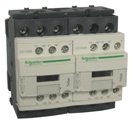


_4_Pole69571.jpg)



-2.jpg?v-cache=1484900302)
-2.jpg?v-cache=1484900302)
