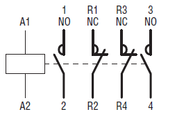
A wiring diagram is a streamlined standard pictorial depiction of an electric circuit. View and download abb irc5 product manual online.
Telemecanique Contactor Lc1 Wiring Wiring Diagrams
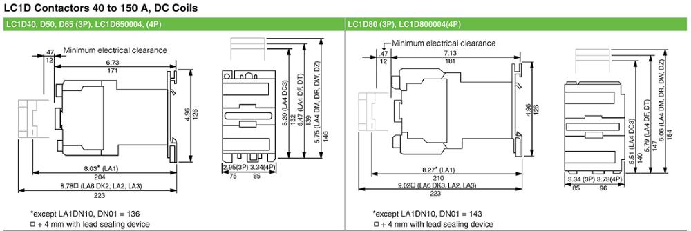
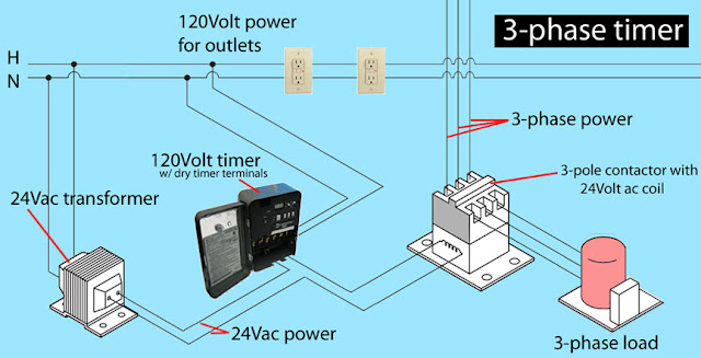
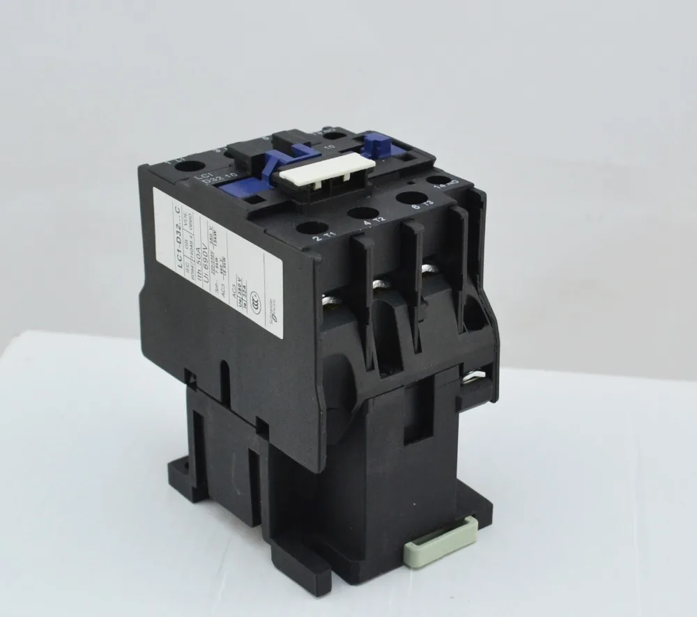
Lc1d32 contactor wiring diagram. This iec contactor comes with 1 normally open and 1 normally closed base mounted auxiliary contacts screw terminals and mounts on standard 35mm din rail. D32 contactor wiring diagram. Schneider electric lc1d32 3 pole contactor rated at 32 amps ac 3 50 amps ac 1 with an ac rated coil choose coil option above. 8 steps with pictures wikihow 2 thoughts on lc1d32 wiring diagram. The lc1d32 is a 3 pole contactor with 1 no and 1 nc base auxiliary contactstelemecanique motor starter wiring diagram wiring libraryhow to wire a contactor. Contactor breakers limit switch no static control standard elementary diagram symbols.
Assortment of schneider lc1d32 wiring diagram. If you are looking for a compact and reliable 20 horsepower. At 460 volt 3 phase 1 normally open and 1 normally closed base mounted auxiliary contacts and screw termination lrd 3 phase overload relays can be added along with top and side mounted auxiliaries for up to 6 additional poles. Main ship equipments equipment types main marine manufacturers an english chinese japanese dictionary of technology abcdefghijklmnopqrstuvw. Interconnecting wire paths may be revealed about where particular receptacles or fixtures should get on a typical circuit. Lc1d32 schneider electric 32 amp contactor with a ac or dc rated coil must specify voltage below rated for 10 hp.
It shows the elements of the circuit as simplified forms and also the power and signal connections between the devices. At 240 volt 20 hp. Wiring diagram book a1 15 b1 b2 16 18 b3 a2 b1 b3 15 supply voltage 16 18 l m h 2 levels b2 l1 f u 1 460 v f u 2 l2 l3 gnd h1 h3 h2 h4 f u 3 x1a f u 4 f u 5 x2a r power on optional x1 x2115 v. Schneider lc1d32 wiring diagram architectural wiring representations reveal the approximate places and affiliations of receptacles lights and also permanent electrical solutions in a structure. 4 table 2 nema and iec terminal markings. Wiring diagram for telemecanique lc1 contactor replacements by us breaker lr aux nc1d aux nc1d aux m control supply voltage is the same as the main circuit voltage 3 phase control supply voltage is not the same as the main circuit voltage 3 phase connect to other supply control supply voltage is the same.
Be sure to set the destination on inverter type frne2se2e 2g 4g 7g for the initial power supply.


