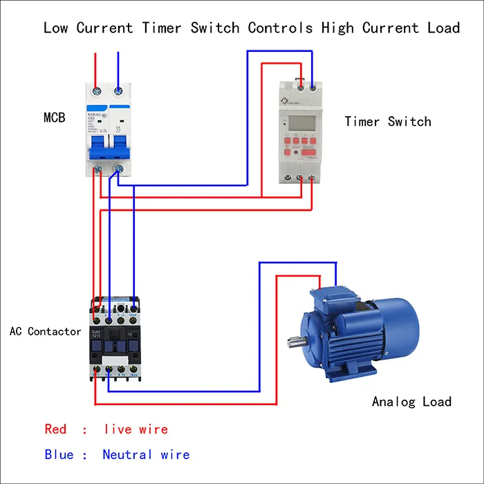
Contactor wiring diagram with timer datasheet. 240 volts ac and 480 volts ac are commonly used for these large pieces of.

Single Phase Motor Starter With Timer Diagram Single Phase
Wiring diagram for timer and contactor. Otherwise the arrangement wont function as it. Many large pieces of equipment are powered directly from high voltage lines. Contactor breakers limit switch no static control standard elementary diagram symbols. 3 phase dol starter control and power wiring diagram. The diagram symbols in table 1 are used by square d and where applicable conform to nema national electrical manufacturers a ssociation. Many large pieces of equipment are powered directly from high voltage lines.
Ryb electrical 88232 views. Electrical earthing methods and types of earthing grounding. With this kind of an illustrative guidebook you will be capable of troubleshoot prevent and complete your projects without difficulty. Contactor controlled by timer tagalog basic motor control electrical ph tutorial. A simple circuit diagram either of the two start buttons will close the contactor either of the stop buttons will open the contactor. Pdf contactor wiring diagram with timer.
Clap switch circuit using ic 555 timer without timer. Contactor wiring diagram you will want a comprehensive professional and easy to know wiring diagram. How to wire a contactor. Water pump controller with float switch duration. How to connect a contactor. Forward reverse electrical interlock wiring tutorial tagalog basic motor control duration.
These lines far exceed the 120 volts ac standard in most homes. Iec contactor specifications bulletin numbers 100104 k 100104 c 100104s c 100104 e 100s e 100104 d 100s d 100 g 100q c topic page.


