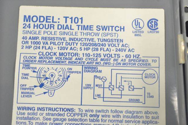
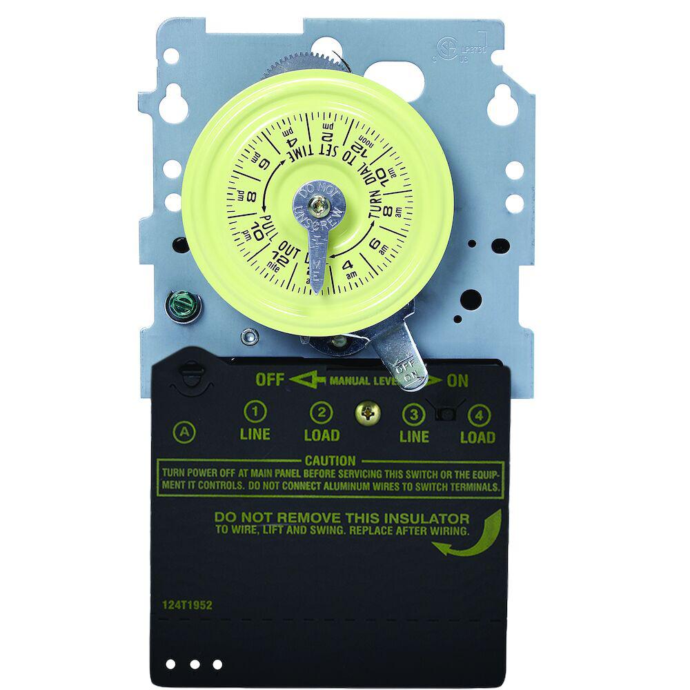
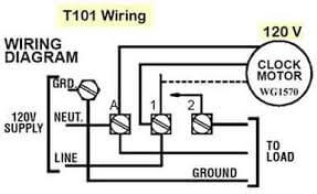
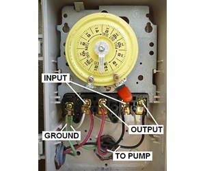
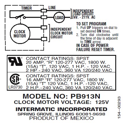
Installing an intermatic t104 timer is a great way to dramatically reduce run time and energy costs. It shows the components of the circuit as simplified shapes as well as the power as well as signal links in between the devices.

Intermatic T101 Wiring Diagram Lihghtings Down3 Zografisch Nl
Intermatic 240v timer wiring diagram. Select the appropriate wiring diagram on page pulse4 and prepare your installation layout. In addition the timer. Will automatically turn the pump onoff low speed if two speed pump for daily. If your intermatic pool timer has stopped working swapping it out is pretty easy. Adjoining wire paths might be shown approximately where certain receptacles or components have to be on an usual circuit. The engineering mindset 1453951 views.
Intermatic incorporated manufactures timer switches designed for indoor and outdoor use. Note timers vary with supply voltage. Intermatic 240v timer wiring diagram building circuitry representations show the approximate locations and affiliations of receptacles lights and also irreversible electrical solutions in a building. Running pool equipment 24 hours is usually unnecessary and expensive. Here i show you how to change a t104m 240 volt 208 277 volt model. Timer intermatic eh10 installation instructions manual electronic 7 day water heater time switches with battery carryover 120v 240v 7 pages switch intermatic et70115c user manual.
Intermatic cell wiring diagram best 06 intermatic et1125. An intermatic timer switch saves electricity when it turns a water heater off at night and when it limits the amount of time a pools filtration system runs. 11 videos play all troubleshooting our intermatic inc. Fresh intermatic pool timer wiring diagram irelandnews. Wiring a 240v outlet step. A wiring diagram is a simplified traditional pictorial representation of an electrical circuit.
Many pool pump motors and water heaters use intermatic timers to regulate their run times. Intermatic t103 wiring diagram download fresh intermatic pool timer wiring diagram irelandnews. Variety of intermatic 240v timer wiring diagram. The following steps will provide a guide on how to install the t104 timer. Lighting contactor wiring diagram with cell rc2163e control. A t104 timer is used for 230v supply voltage.
Model r8806p101c peter pa 120v 240v electricity explained split phase 3 wire duration. Two speed pump. Subscribe to our newsletter sign up for email alerts for products and software updates new product releases and information about upcoming events.

