The simplest form of motor starter for the induction motor is the direct on line starter. The dol starter is made of a circuit breaker or mccb or fuse an overload relay and contactor or coil.

Ls3 Starter Motor Wiring Diagram Diagram Base Website Wiring
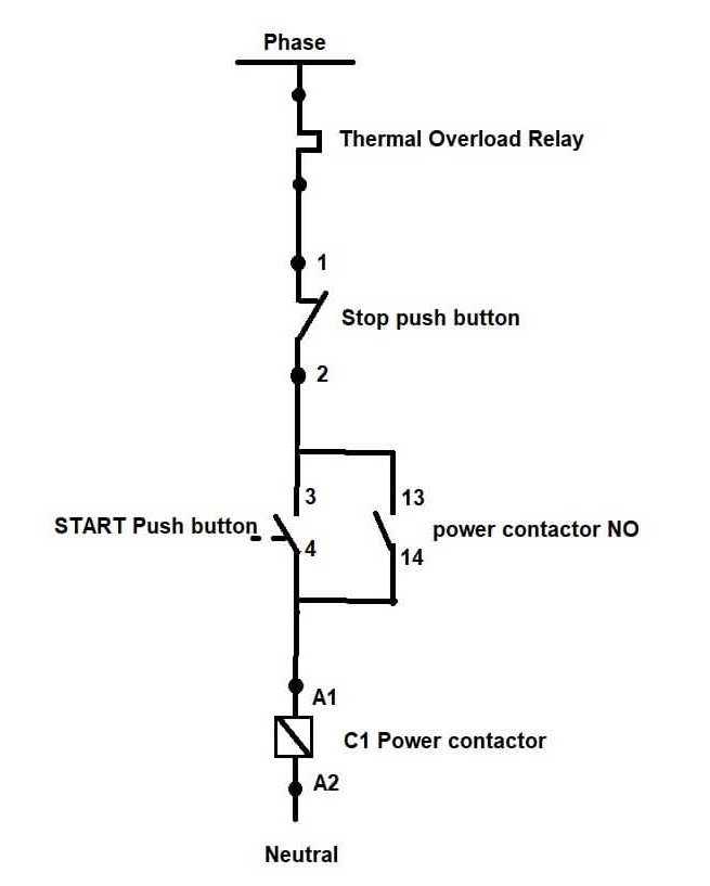
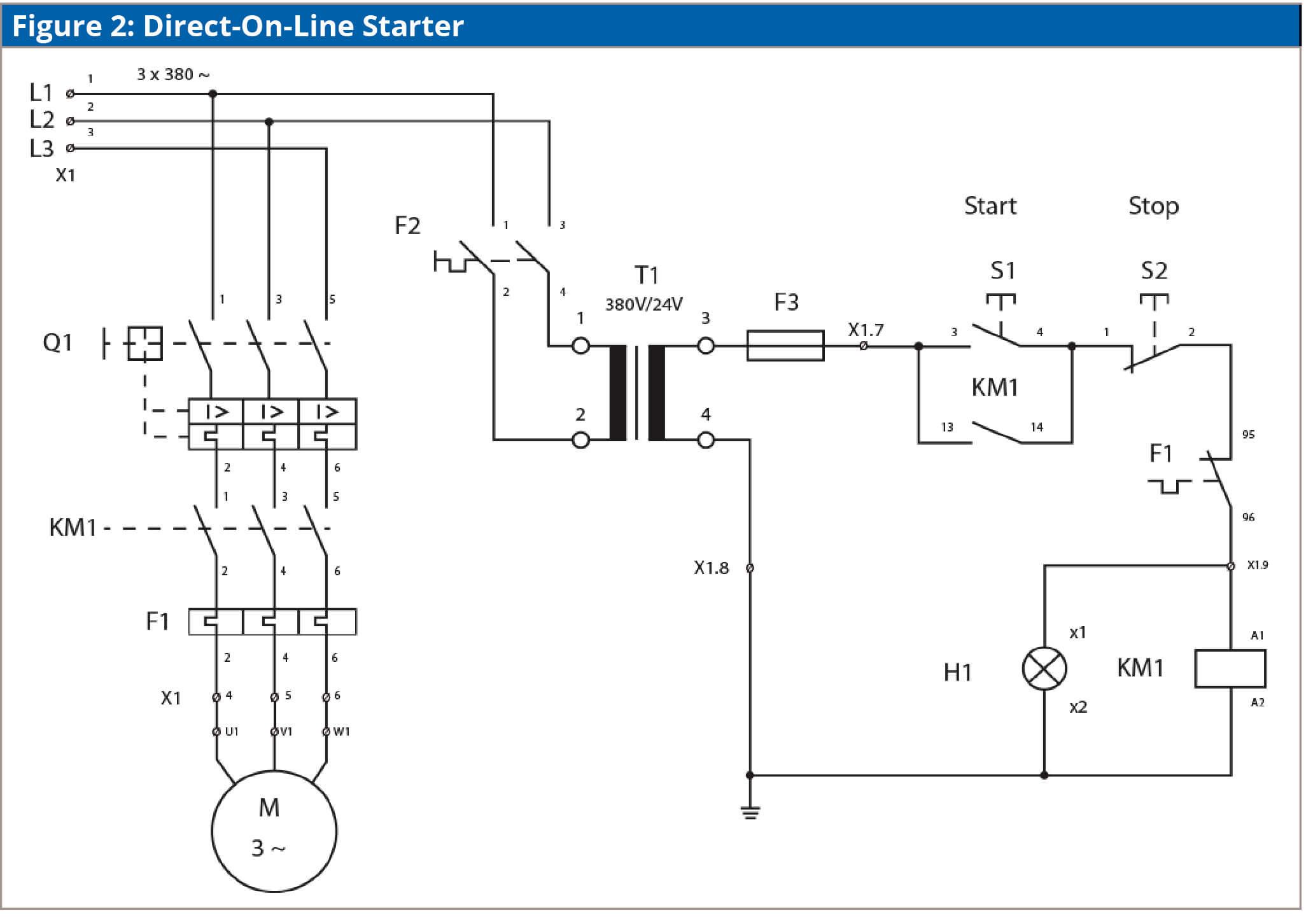
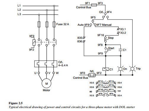
Dol motor starter wiring diagram. A wiring diagram of a dol starter is. The contactor is used for starting and stopping the motor where the green and red buttons are connected. The direct on line motor starter dol consist a mccb or circuit breaker contactor and an overload relay for protection. The 3 phase dol starter wiring diagram is shown below. Electromagnetic contactor which can be opened by the thermal overload relay under fault conditions. In the above three phase dol starter wiring diagram.
Despite this direct connection no harm is done to the motor. The circuit breaker is used for protection against short circuits while the overload relay protects the motor from overloading. In the below dol starter wiring diagram i shown a molded case circuit breaker a magnetic contactor normally open push button normally close push button switch thermal overload relay motor trip indicator and 3 phase motor. In dol starter an induction motor is connected directly across its 3 phase supply and the dol starter applies the full line voltage to the motor terminals. A dol motor starter contains protection devices and in some cases condition monitoring. Between the mains supply terminals and motor terminals the dol starter main terminals are connected and with the two terminals of the three phase power supply as described in figure 1 the control circuit is energized.
I dol starter wiring connection with start and stop buttons are shown in the above figure 1. The dol starter joints the 3 phase main wiring with the induction motor namely l1 l2 and l3 when the start switch is pressed. And one wiring is called controlling wiring. Generally the direct online starter working can be done in two different stages namely dol starter control circuit and dol starter power circuit.


