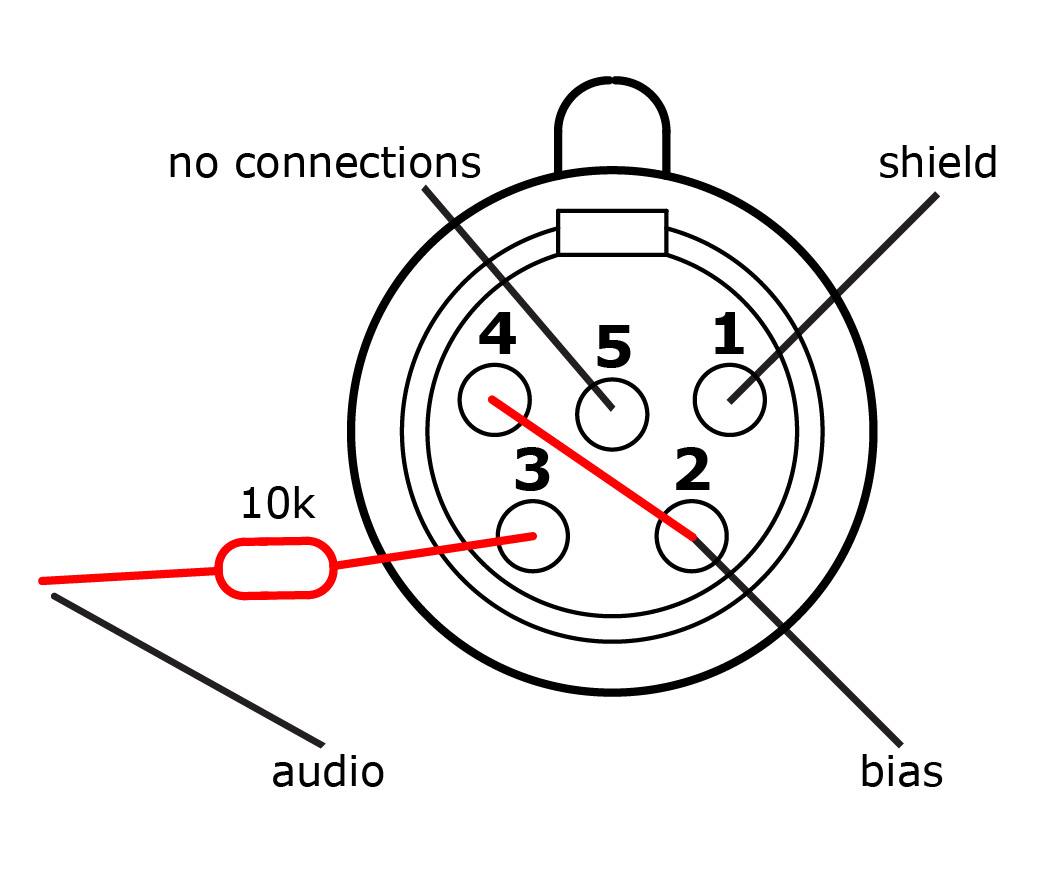
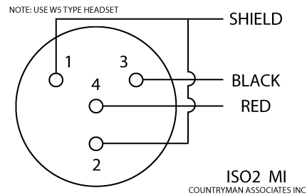
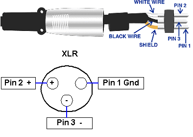
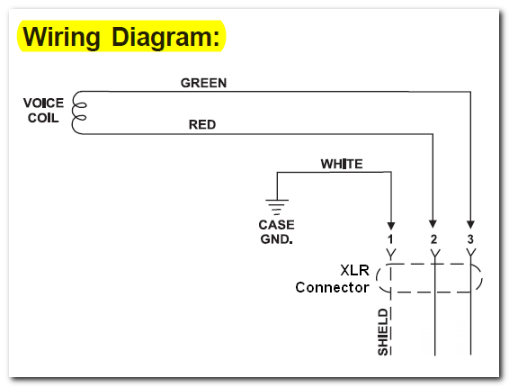
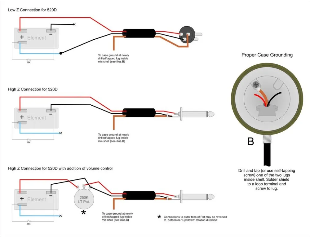
3 pin xlr audio pinout. Any helpful comments.

About Generic Tube Mic Psu And M49 Build Updated
Xlr microphone cable wiring diagram. Collection of xlr wiring diagram pdf. 3 pin xlr connectors are standard amongst line level and mic level audio applications. The following is the aes industry standard for balanced audio xlr wiring commonly known as pin 2 hot. Here is the essentials for soldering xlr and mic cables. The most comon way to wire a 3 pin xlr to a 14 inch 65mm mono plug sometimes called a jack plug is to join the negative and shield together. Pyle microphone xlr to usb signal adapter universal plug and play xlr mic to pc adaptor for digital recording w mix audio control 48v phantom power headphone volume usb cable pdusbpp10 43 out of 5 stars 129.
Xlr to 14 mono plug. The surrounding shield should be soldered to pin 1. Connection xlr jack to jack pin male xlr to female xlr duration. This can be done by either soldering the shield and negative wires of the xlr to the sleeve of the plug. Pin 2 on the xlr is hot and carries the positive going signal whilst pin 3 is cold and provides the return. The above diagram shows you the pin numbering for both male and female xlr connectors from the front and the rear view.
Xlr cable 1 jpg xlr wire diagram wiring microphone solutions xlr wiring diagram new clear 3 pin headset audio xlr wiring diagram free diagrams. If you dont have time to watch a massive video on soldering technique. 3 pin xlr wiring diagram cable wiring etc cable designed for being cut into standard mic cables may have 2 pairs of wire and a shield around the outside in that case pair the colors together and make sure they go to the same pin number on each end. Dan baker 23140 views. Xlr microphone cable repair soldering tutorial duration. 3 pin xlr wiring standard.
The rear view is the end you solder from here are the connections on each pin. The above diagram shows you the pin numbering for both male and female xlr connectors from the front and the rear view. Xlr pinout balanced a balanced system is used in pro audio systems xlr wiring diagram shown below with an overall screen covering a twisted pair. Some manufacturers especially in vintage equipment do not follow this standard and instead reverse the polarity of pin 2 and 3. It shows the elements of the circuit as simplified forms and the power and also signal connections between the tools. A wiring diagram is a simplified standard photographic depiction of an electric circuit.


