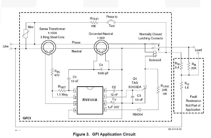
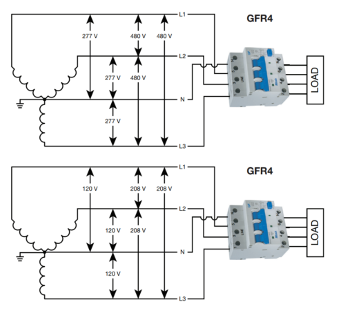
Gfci also known as ground fault circuit interrupter is a protective device which automatically detects the ground faults and leakage current and provides personal protection against electrocution. So gfci designed as checking the difference between the current leaving and returning through current transformer of the gfci to protect device exceeds 5ma.

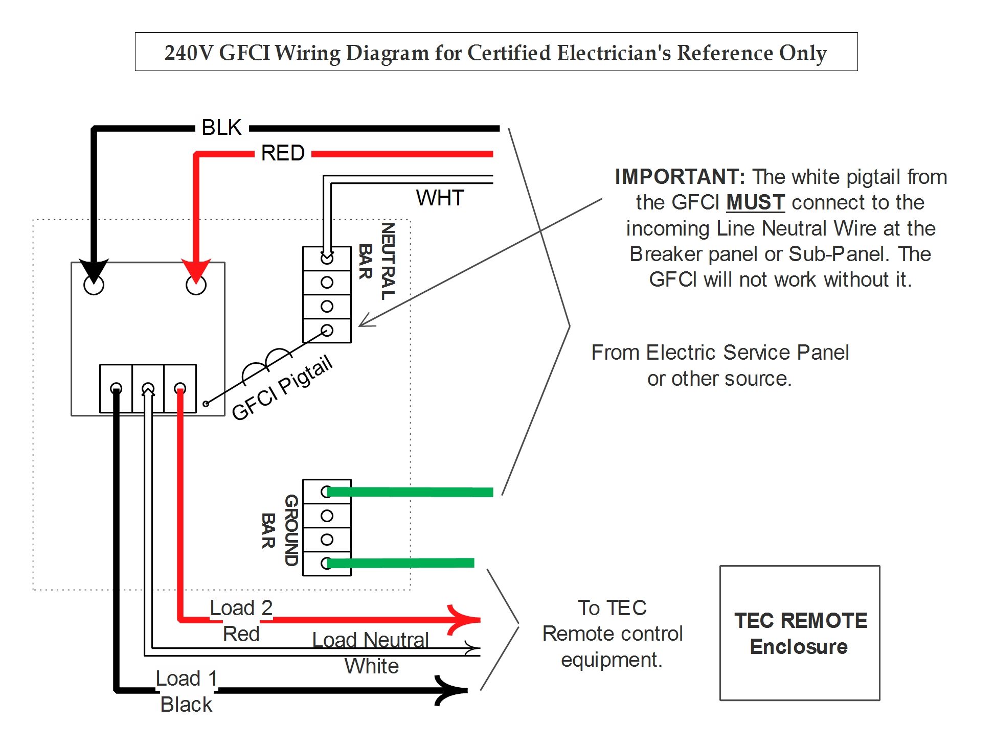
Pool Gfci Breaker Wiring Diagram Bmwiok 7 Mareikekirsch De
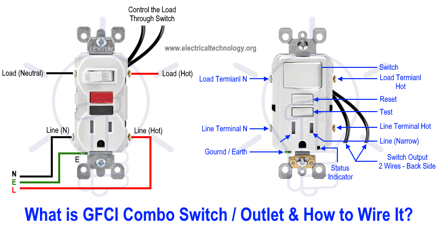
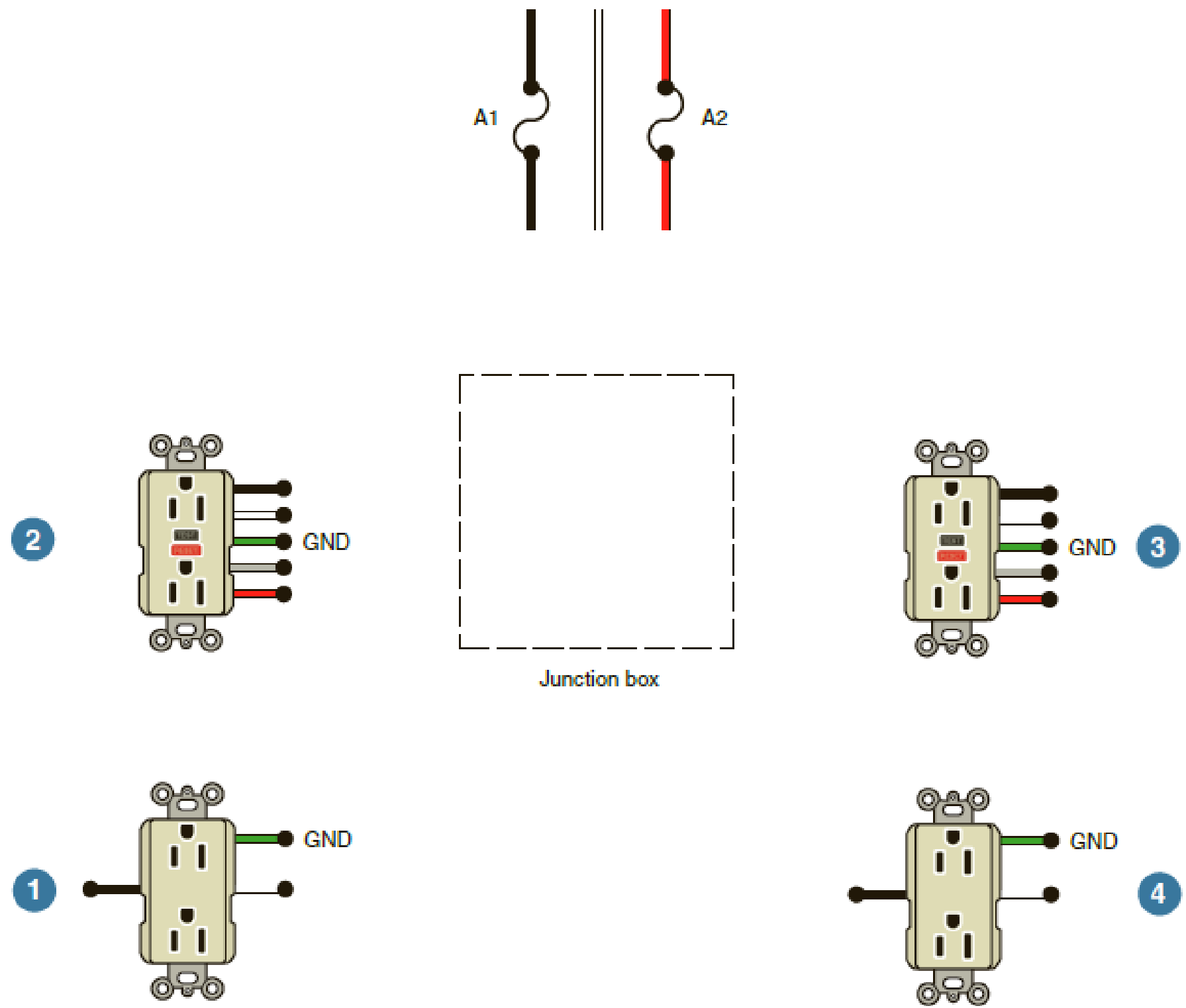
Gfci circuit diagram. A typical application for this method would be to protect more than one bathroom or the all of the receptacles in your garage. The line terminals of a gfci outlet connect to the power supply conductors that are connect at the circuit breaker or fuse box. This diagram illustrates the wiring for multiple ground fault circuit interrupter receptacles with an unprotected duplex receptacle at the end of the circuit. In the gfci mainly two wires connect as also shown in a diagram the current flowing from the source and coming back are some due to current laws. Gfci circuit breakers last longer than gfci outlets and are a good idea if you do not test your gfci outlets on a regular basis. Gfci outlet wiring diagram.
Refer to the attached gfci outlet wiring diagram above for clarity or contact our in office electrician in mesa az free of charge. Read on to learn more about proper installation. The ground fault circuit interrupter gfci saves lives. Protecting more than one receptacle from one gfci this method is used when installing the gfci as the first receptacle and wiring it so that it provides protection for all of the receptacles downstream on the circuit. Gfci as an outlet receptacle combo or circuit breaker automatically cuts off the main power supply within millisecond against electric shock. Line essentially means supply.
There are two different kinds for home use electrical outlets and circuit breakers. Gfci receptacle in a series with an unprotected outlet. The load terminals on the gfci are not used and the last receptacle is wired directly to the circuit source.


