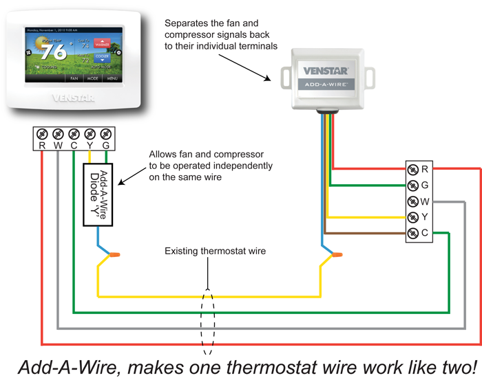
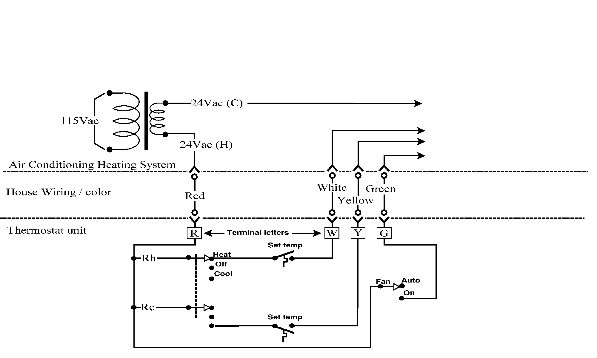
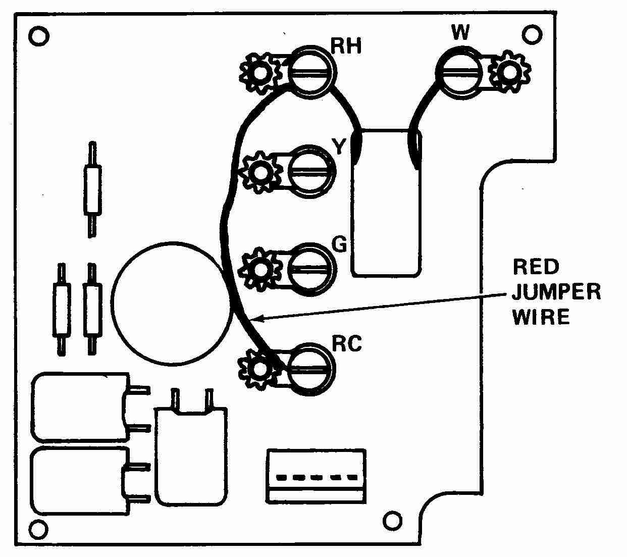
I show where the wires go at the thermostat the color code then down at the furnace control board and how to wire up the wires coming. The basic heat ac system thermostat typically utilizes only 5 terminals.

Home Thermostat Wiring Wiring Diagram
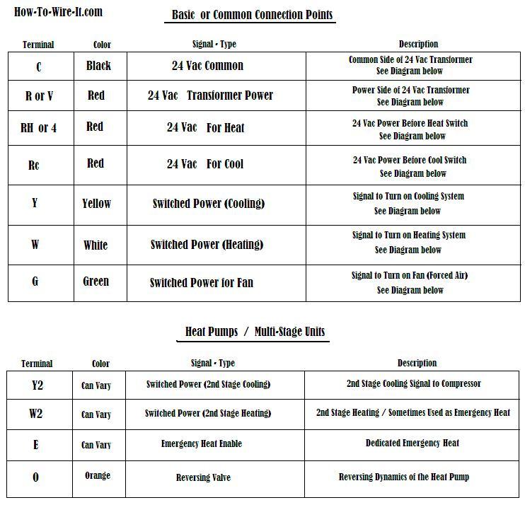
Simple thermostat wiring diagram. The diagram below shows how a basic 4 wire thermostat is connected as indicated by the color code chart above. Thermostat wiring diagrams furnaces. This way you have a reference. Before uninstalling the old thermostat take a picture of the wiring with your cell phone before removing the wires. The thermostat is the control device that provides a simple user interface with the internal workings of your homes climate control system. Heating only thermostat wiring diagrams if you only have a furnace such as a gas furnace oil furnace electric furnace or a boiler.
It corresponds to the chart below to explain the thermostat terminal functions. Basic thermostat wiring for furnace and air conditioner. Rc red wire power 24 vac rh or 4 red wire jumpered power 24 vac. Therefore you will use the following color code for simple thermostat wiring. This originates from the transformer. Terminal r or terminal rh for the red wire.
And it has been recorded by a professional in the industry. If youre still a little confused and i can understand why you would be i have added a thermostat wiring made simple video for you to look at which isnt very long but is one of the best explanations i have come across. By the use of an adjustable set point the job of the thermostat is to turn on either the heating or cooling system to maintain the desired room temperature in the home and to turn off the system when the desired temperature is achieved. Heat pump thermostat wiring chart diagram. The basic heat pump wiring for a heat pump thermostat is illustrated here.

