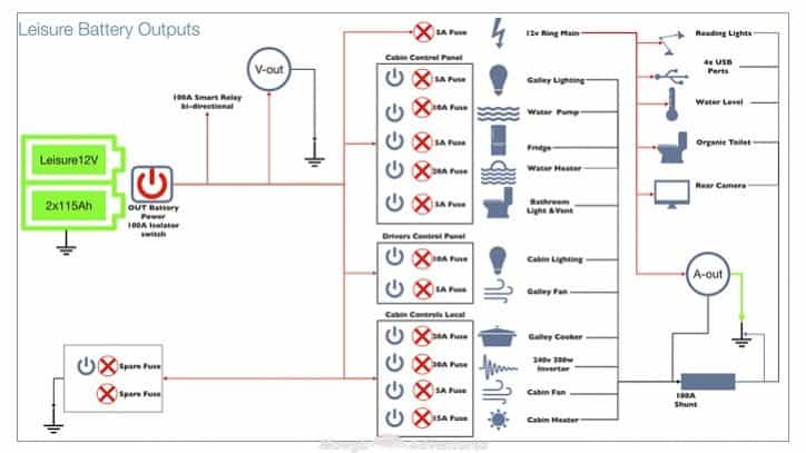
That said for specific situations there are industrial standards with different connectors and wire arrangements. One rv two electrical systems.
Basic Camper Wiring Diagram H1 Wiring Diagram
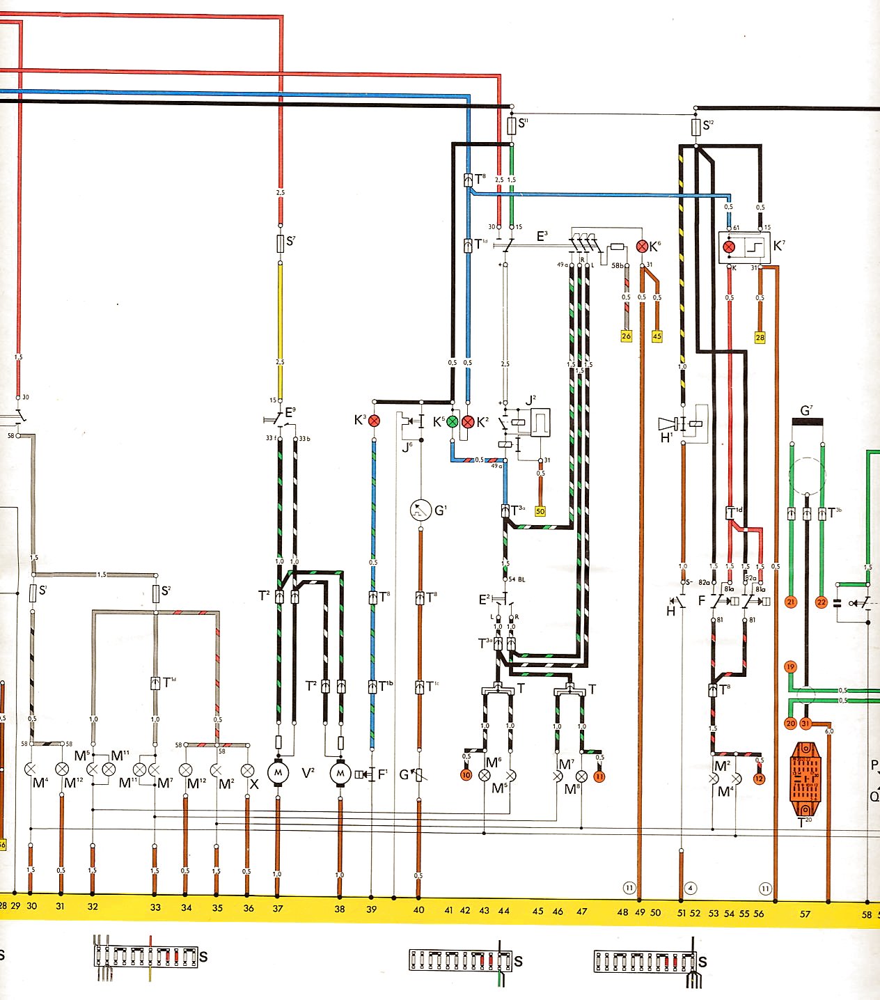
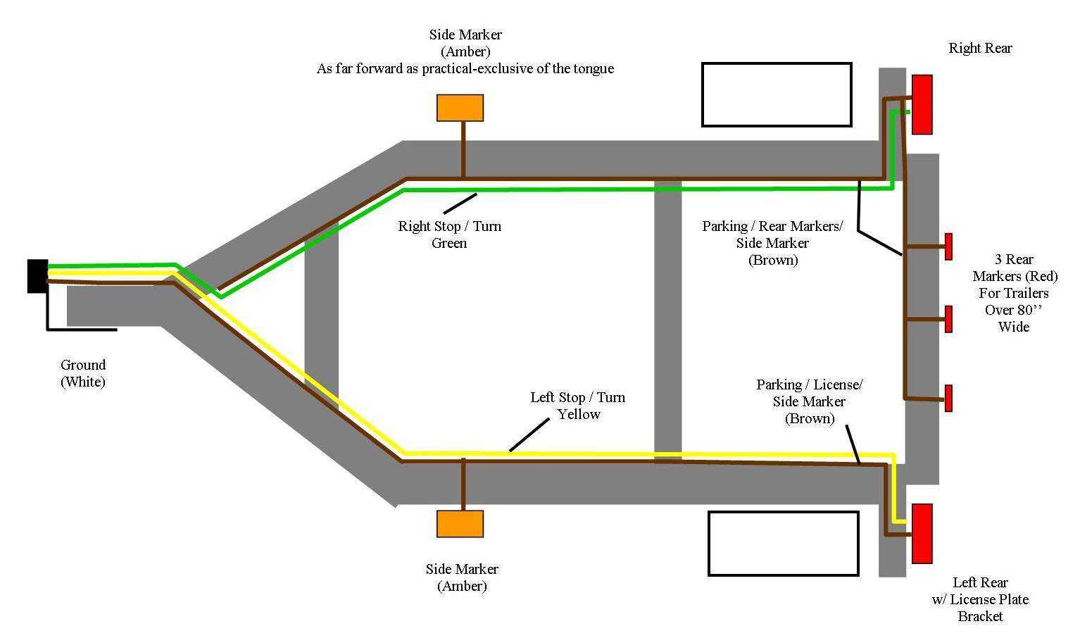
Camper electrical wiring diagram. The following trailer wiring diagrams and explanations are a cross between an electrical schematic and wiring on a trailer. Your rv has two separate electrical systems. We recommend these standards because they are pretty universal. The 12 volt system is powered by a battery or in some cases multiple batteries and it powers things such as the start up on your water heater furnace and refrigerator plus most of the lights in your rvs living space your water pump your carbon. A wiring diagram is a streamlined traditional photographic depiction of an electric circuit. Trailer wiring diagram wiring diagrams for trailers international 1 989 755 0561 toll free 1 800 358 4751 covid 19.
A 12 volt dc electrical system and a 120 volt ac system. Use this handy trailer wiring diagram for a quick reference for various electrical connections for trailers. Complete with a color coded trailer wiring diagram for each plug type this guide walks through various trailer wiring installation solution including custom wiring splice in wiring and replacement wiring. Free wiring diagram and tutorial inside. If your vehicle is not equipped with a working trailer wiring harness there are a number of different solutions to provide the perfect fit for your specific vehicle. Collection of travel trailer wiring schematic.
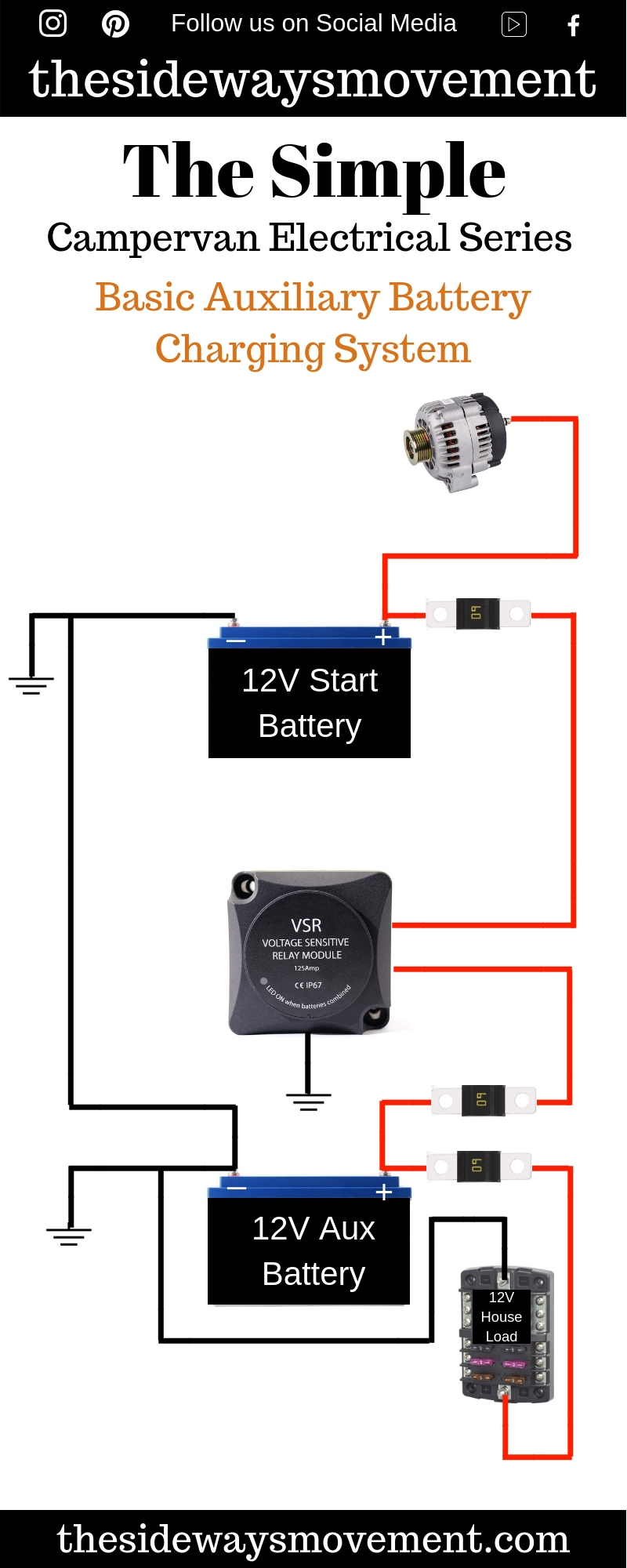
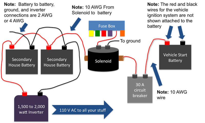
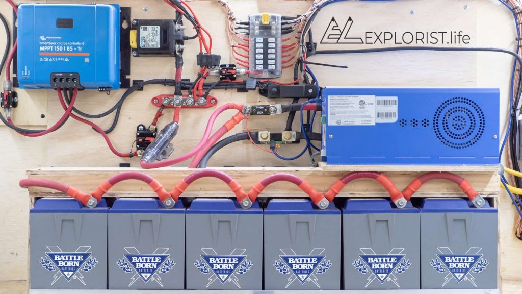
It reveals the parts of the circuit as streamlined shapes as well as the power and also signal links in between the gadgets. Complete guide on designing and installing your own diy electrical system in a camper van conversion.

