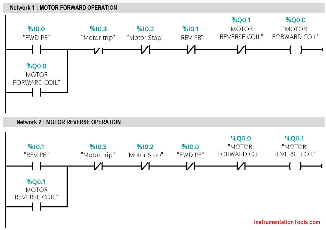
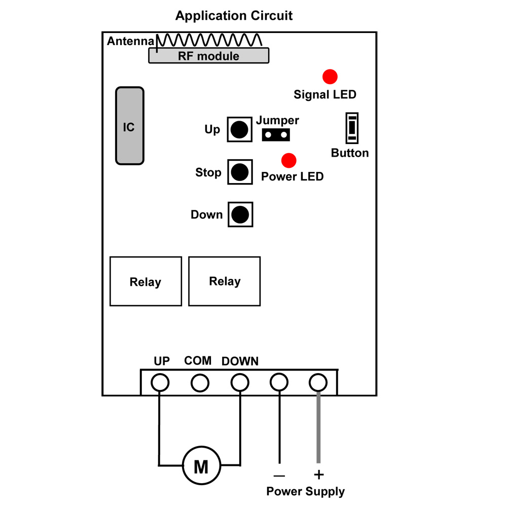
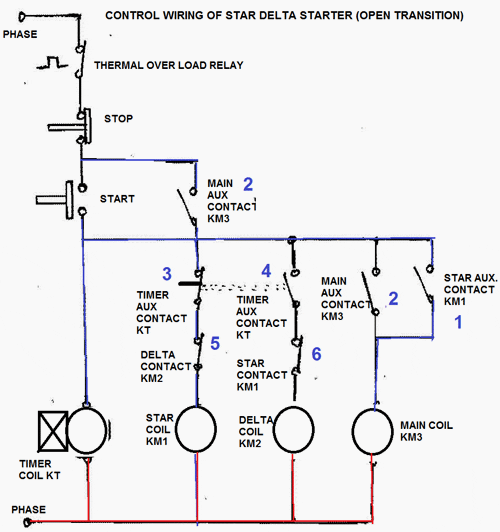
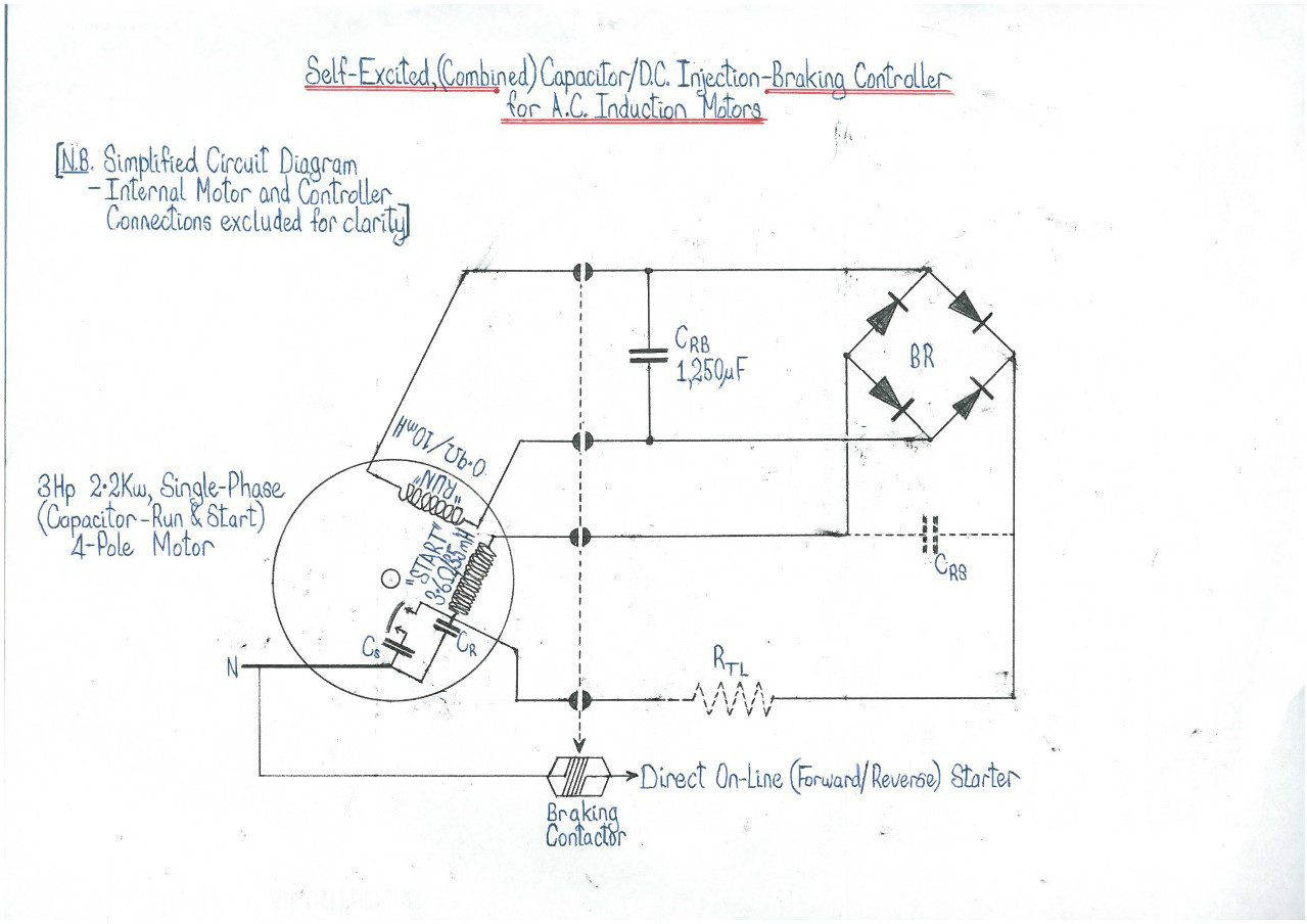
In this post you will complete learn about the forward reverse three phase motor controlling starter diagram. As the name defines forward reverse starter is used to run the motor in both sides forward and reverse.

Vb 8056 Dol Power Circuit Dol Reveres Forward Power Circuit
Forward reverse starter pdf. The supply can not the the other conductor because nc and no. Forward reverse motor starter circuit क बर म जनन स पहल यह जन लन आवशयक ह क forward reverse motor क उपयग कह हत ह जब हम कह पर मटर क दन सइड घमन क आवशकत हत ह. Pressing the reverse push button r will energize contactor r. In the 3 phase motor forward reverse starter wiring diagram. Maintaining contact r13 14 will close to maintain contactor r continually energize evenif the reverse push r button is release. Figure 5 forwardreverse motor wiring diagram.
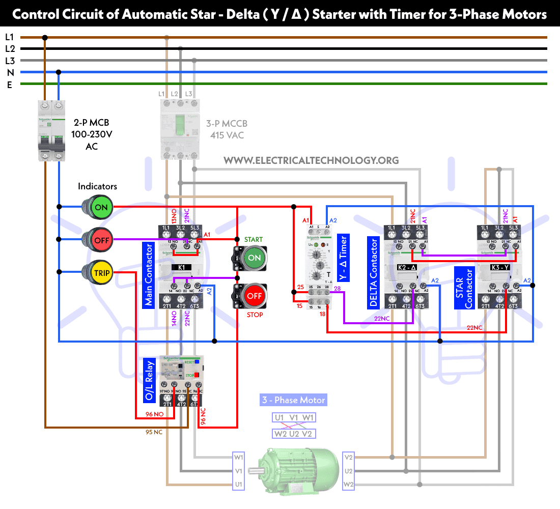
In the event of an overload both motor starter output. The figure given below shows the control and power diagram of forward and reverse starter diagram. Control circuit of dol starter control circuit of fully automatic starter auto transformer working and saving in copper material speed control of dc series motor. There is problem in control drawing because when motor runs forward or reverse then we can not change its state to forward or reverse by its push button. Three phase motor connection stardelta y δ reverse and forward with timer power control diagram as we have already shared the starting method of three phase motor by star delta starter with timer circuit power and control circuits. When we push the stop button it may stop working.
Contacts r11 12 will open to prevent contactor f to be energized. Contacts r 1 2 3 4 5 6 will close to run motor m on reverse direction. Variety of single phase motor wiring diagram forward reverse. Three phase slip ring rotor starter control power diagrams. In this article we are going to learn about the forward reverse starter. This forward reverse starter can start the machine in two ways clockwise and anti clockwise.
Now in the below diagrams three phase motor will rotate in two directions viz forward and reverse. The overload contacts are connected to l1 on one side and to the plcs input module on the other input 003. Control circuit of forward reverse starterpdf you may also like. I shown the 3 pole mccb circuit breaker 2 magnetic contactor normally open normally close push button switch thermal overload relay 3 phase 4 wire system supply 3 phase. A wiring diagram is a simplified conventional pictorial representation of an electrical circuit. Forward reverse starter diagram.
62 as the name suggests this motor starter is used where the motor needs to rotate in both sides clockwise and anti clockwise. On off three phase motor connection power control diagrams. In this wiring diagram both the forward and reverse coils have their returns connected to l2 and not to the overload contacts. It reveals the components of the circuit as simplified forms as well as the power as well as signal links in between the tools.
