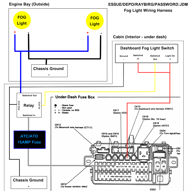
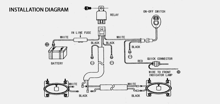
In this wiring diagram the switch is a direct fit switch but the wiring procedure will be the same for both switches. 2 connect black wire to battery negative.
A Fog Light Wiring Diagram Wiring Diagram
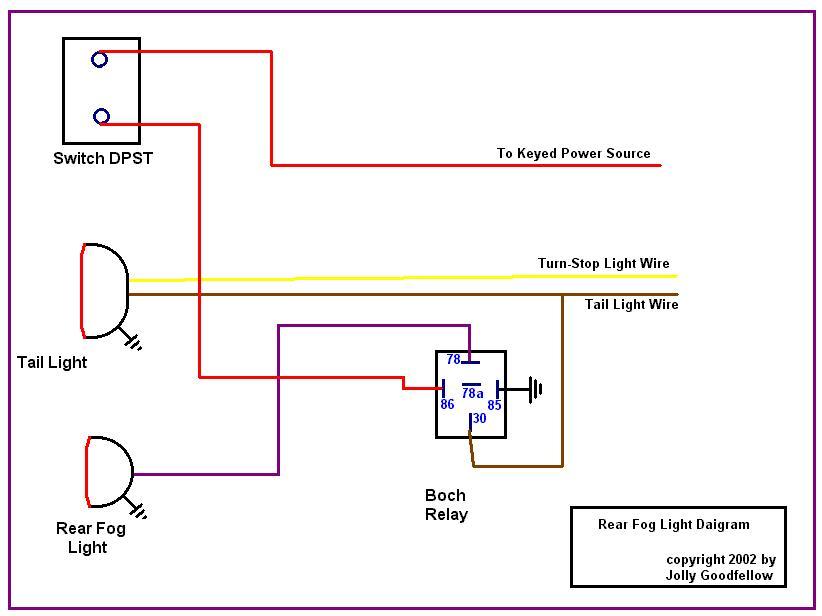
Fog light wiring diagram with relay. Fog light relay wiring diagram positive ground wiring library fog light wiring diagram with relay. Fog lights off with high beams on relay wiring diagram. Power 12v to the fogs lights passes through the normally closed contacts of the relay terminals 30 and 87a. Fog light wiring diagram with relay. This hook up does away with the headlight lamp connection. Loosen the stud or bolts securing the fog or driving lamp to the bracket to adjust the lights up or down.
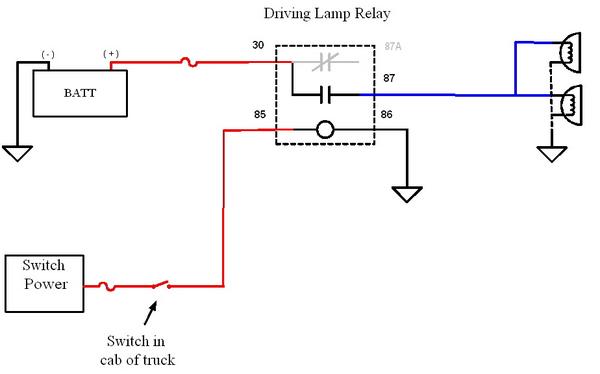
With our wiring harness all you need to do is cut the wire coming from the switch to the 30 prong on the relay and wire it to your high beam lead or your backup light wire. 30 and 87 create the switch to your lights. When the coil of the relay is energized 12v from the high beam switch to terminal 86 ground on terminal 85 the normally closed contacts open interrupting 12v to the fog. This must be done for the switch the relay and each of the fog lights. The etiquette rules for fog lights are the same as for bright high beams. Wiring diagram comes with a number of easy to stick to wiring diagram instructions.
Green wire connects directly to the battery to power switch relay. These instructions will probably be easy to grasp and use. It is for this reason that we present here the proper way to wire a fog light. 3 connect red wire to battery positive. Drill the required hole in your dash for the switch. 1 the two connectors will be connected to the fog light assembly.
Leave the switch free for the moment. You dont want to blind the other driver. That is kind of cryptic isnt it. It is for this reason that we present here the proper way to wire a fog light systems. How to wire your light using a relay the relay will have 4 points on it marked 30 87 85 and 86. Pictured is my wiring diagram for installing two fog lights with fuses a switch and a relay.
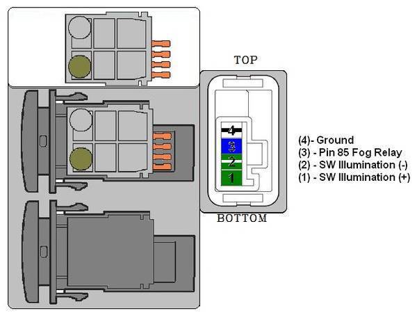
The left side is the pin out of the point is sticking out from at the bottom and the the right side is showing a schematic representation of the relay circuitry. I like to start wiring everything together at the switch and work my way toward the relay and the front of the car. 4 connect yellow wires from the switch and the relay together. It is meant to aid all the typical consumer in creating a correct system. Failure to do so would cause excessive heat in the wiring and switch and create a risk of fire. The relay ground terminal is numbered 85.
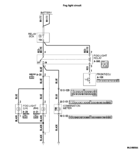
That way when you do have your high beams on the current from that goes to the dash switch first and if that is off the electricity cant get to the 8586 circuit to. Alternative fog or driving light schematic.

