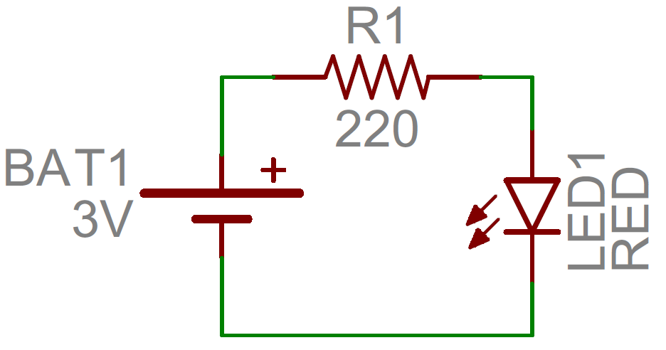
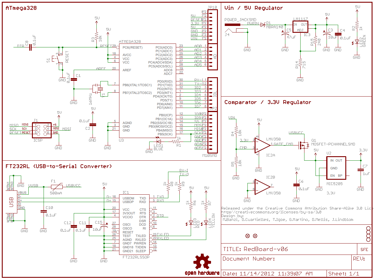
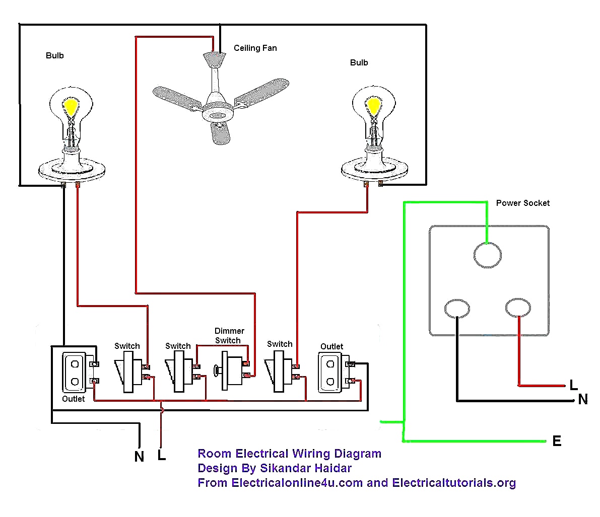
With the light at the beginning middle and end a 3 way dimmer multiple lights controlling a. To read electrical schematics the fundamental electrical schematic symbols should be understood.

Symbols Used In Circuit Diagrams Get Free Image About Wiring
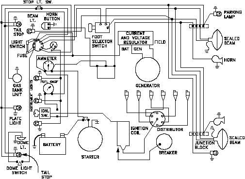
Electrical wiring schematic. Wiring diagrams for 3 way switches diagrams for 3 way switch circuits including. Residential electric wiring diagrams are an important tool for installing and testing home electrical circuits and they will also help you understand how electrical devices are wired and how various electrical devices and controls operate. Knowing component symbols following nets and identifying common labels. Wiring diagrams for receptacle wall outlets diagrams for all types of household electrical outlets including. Understanding how a schematic works opens up the whole world of electronics to you. The basics of boat wiring.
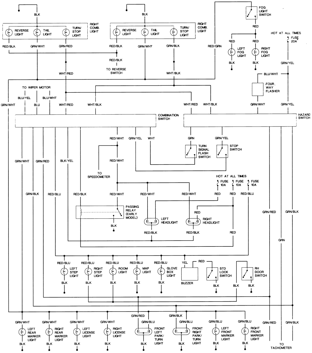
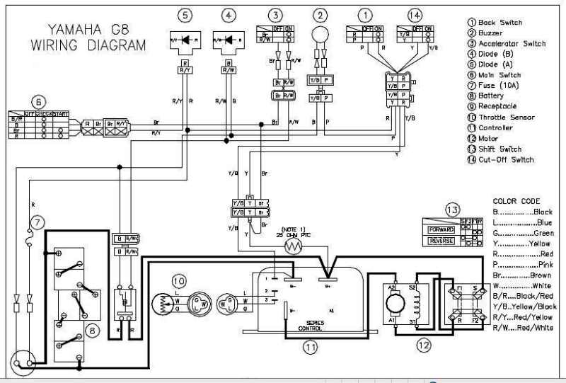
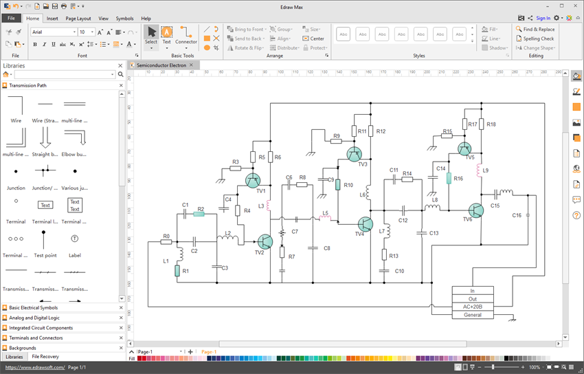
An electrical schematic is a logical representation of the physical connections and layout of an electric circuit. Basics 13 valve limit switch legend. A well documented schematic outlines the functionality of an electric circuit and provides the basis for assembly and troubleshooting of a system. Basics 16 wiring or connection diagram. Here is a standard wiring symbol legend showing a detailed documentation of common symbols that are used in wiring diagrams home wiring plans and electrical wiring blueprints. 800 x 600 px source.
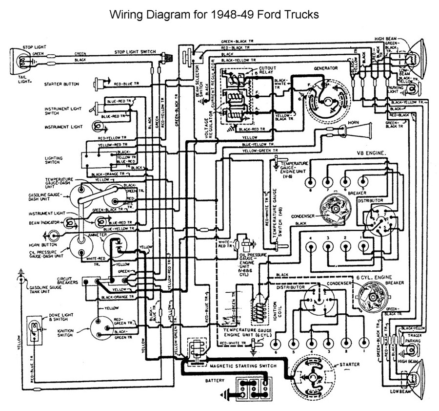
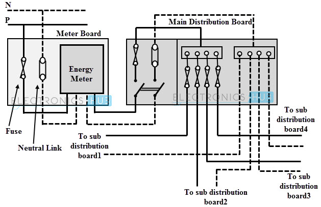
Basics 9 416 kv pump schematic. Basics 14 aov schematic with block included basics 15 wiring or connection diagram. Wiring diagrams show how the wires are connected and where they should located in the actual device as well as the physical connections between all the components. Then well talk about how those symbols are connected on the schematics. Wiring schematics pictures best practices and tips to get your boats electrical systems in shape. Thats all there is to schematic reading.
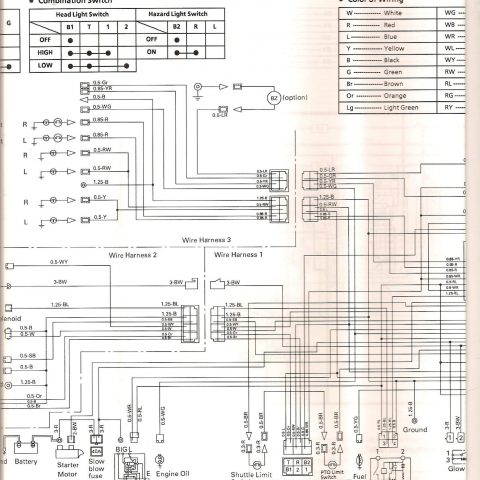
Check out some of these tutorial to practice your new found schematic knowledge. Voltage dividers this is one of the most basic fundamental. Wiring diagram diagnostics 1. Basics 11 mov schematic with block included basics 12 12 208 vac panel diagram. A schematic shows the plan and function for an electrical circuit but is not concerned with the physical layout of the wires. Here are a few of the leading illustrations we get from different sources we hope these pictures will be useful to you and ideally extremely appropriate to what you want regarding the 2003 ford f 150 electrical diagram is.
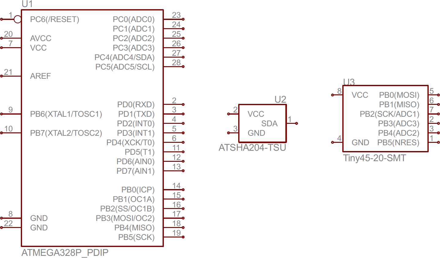
2003 ford f 150 no start theft size. Wiring diagrams use simplified symbols to represent switches lights outlets etc. Basics 10 480 v pump schematic. Recognizing electrical schematic symbols here are some of the standard and baisc symbols for various components for electrical schematics. Duplex gfci 15 20 30 and 50amp receptacles.
