An ac motor converts electric energy into mechanical energy. In an induction motor the rotor always turns at a lower speed than the field making it an example of whats called an asynchronous ac motor.

Ac Motor Speed Picture Speed Control Of Ac Motor Using Scr
Ac motor diagram. Before deepen in steps of drawing the diagram it. Ac fan motor wiring diagram youll need a comprehensive expert and easy to know wiring diagram. The rotor magnetic field may be produced by permanent magnets reluctance. The theoretical speed of the rotor in an induction motor depends on the frequency of the ac supply and. Based on your observations of these two diagrams explain how electromechanical relays are represented differently between ladder and schematic diagrams. Ac80 ac90 ac100 single phase motors.
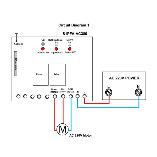
As 183 wiring diagram with switch. With this sort of an illustrative guidebook you will have the ability to troubleshoot avoid and complete your assignments with ease. Diagram er9 m 3 1 5 9 3 7 11 low speed high speed u1 v1 w1 w2 u2 v2 tk tk thermal overloads two speed stardelta motor switch m 3 0 10v 20v 415v ac 4 20ma outp uts diagram ic2 m 1 240v ac 0 10v outp ut diagram ic3 m 1 0 10v 4 20ma 240v ac outp uts these diagrams are current at the time of publication check the wiring diagram supplied with. Ac motors are at the heart of the electrical consumption in the world because they do so much and with very little human intervention. An ac motor is an electric motor driven by an alternating current ac. 4 wire reversible psc motor.
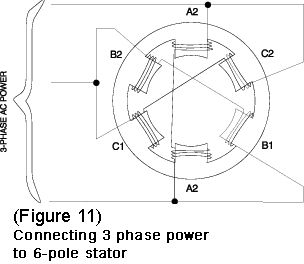
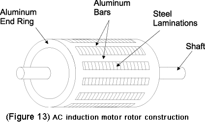
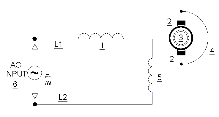
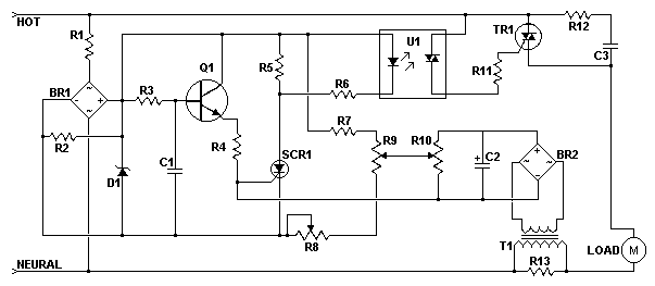
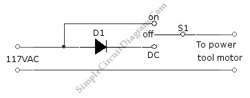
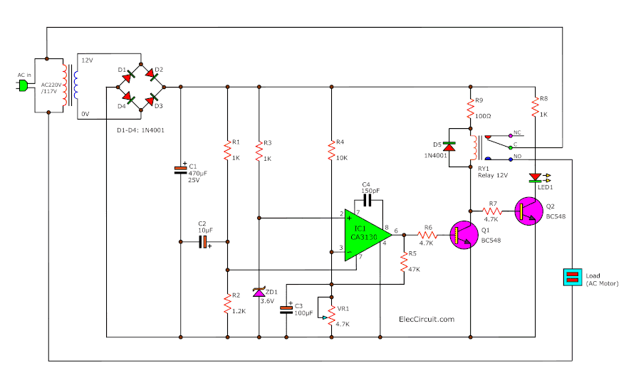
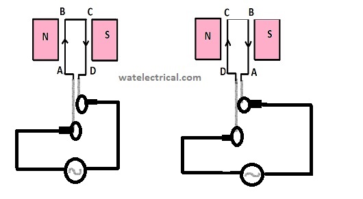
An ac motor uses alternating current in other words the direction of current flow changes periodically. The ac motor commonly consists of two basic parts an outside stator having coils supplied with alternating current to produce a rotating magnetic field and an inside rotor attached to the output shaft producing a second rotating magnetic field. Also explain the operation of this motor control circuit. In the case of common ac that is used throughout most of the united states the current flow changes direction 120 times every second. Interpret this ac motor control circuit diagram explaining the meaning of each symbol. This triac based 220v ac motor speed controller circuit is designed for controlling the speed of small household motors like drill machines.
To understand the circle diagram of induction motor we should first know what is the circle diagram. Circle diagram of induction motor. The circle diagram is a graphic representation of the performance of the machine and its drawn in terms of the locus of the input voltage and current. The speed of the motor can be controlled by changing the setting of p1. In synchronous ac motors the rotor turns at exactly the same speed as the rotating magnetic field. And its based on the approximate equivalent circuit.
Ac80 ac90 ac100 single phase motors. The setting of p1 determines the phase of the trigger pulse that fires the triac. An ac alternating current motor is an electromechanical device that converts electrical energy into mechanical movement through the use of electromagnetism and the changing of the frequency and voltages produced by the utility company or motor controller.
