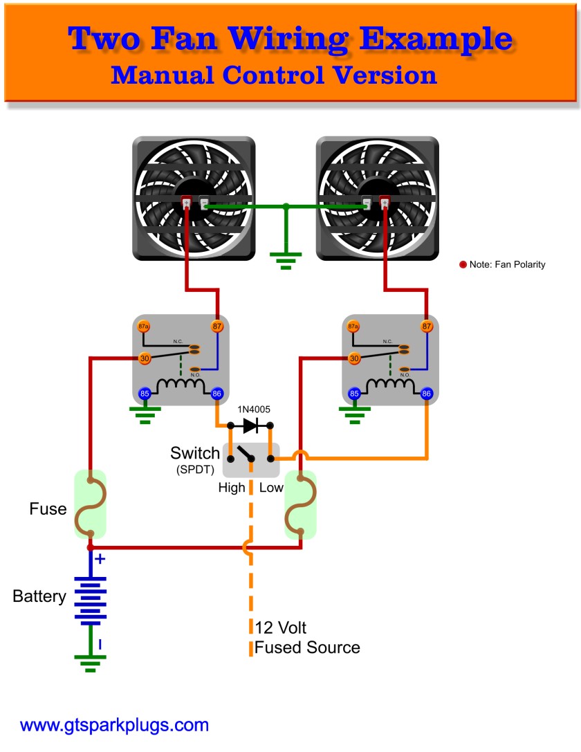
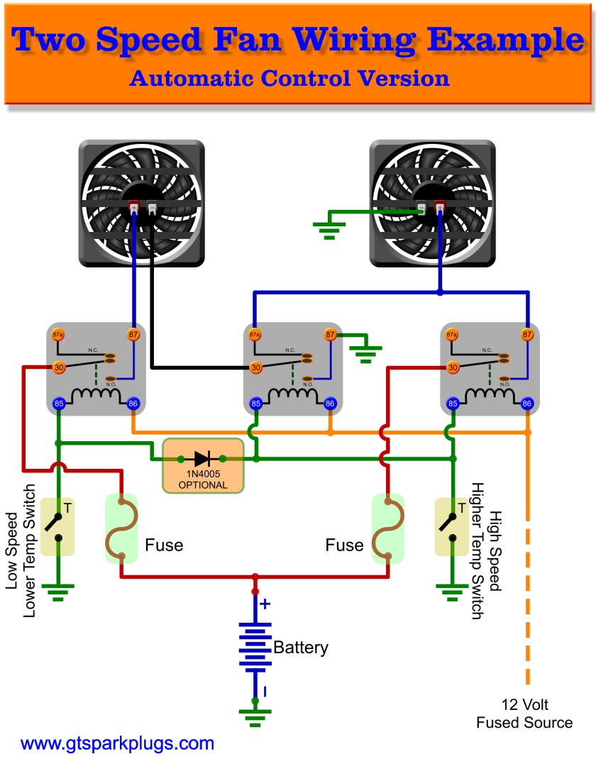
Gone are the days when the control method was a simple resistor. Delta series twin fan a 2223 diags.
Dodge Caliber Manual Part 784
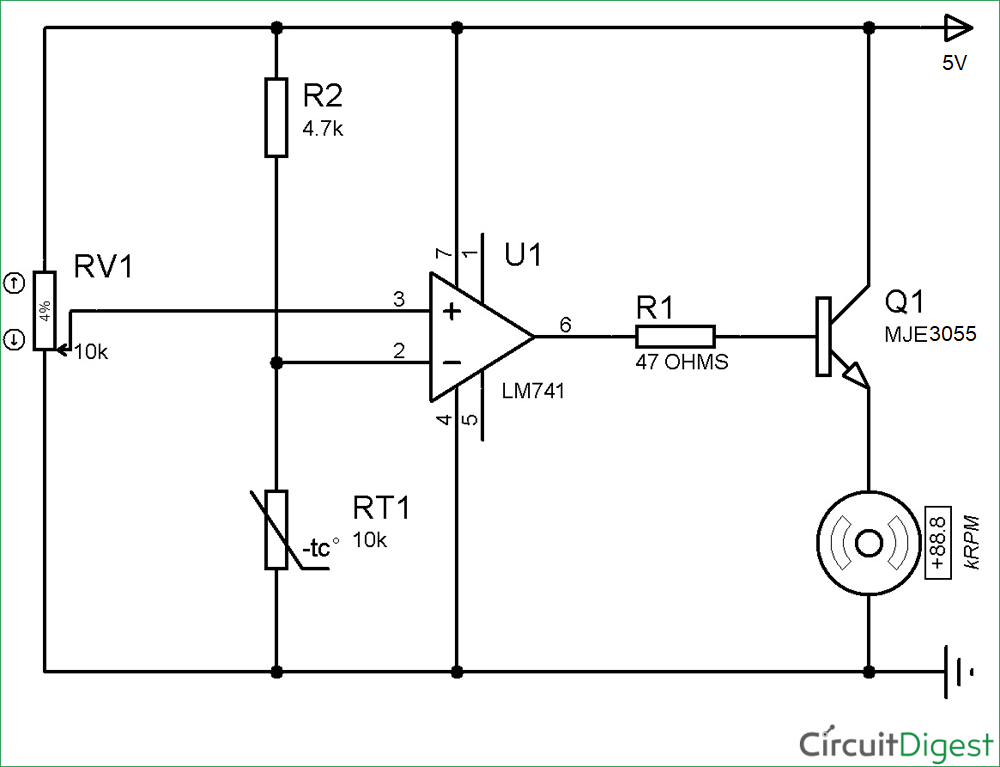
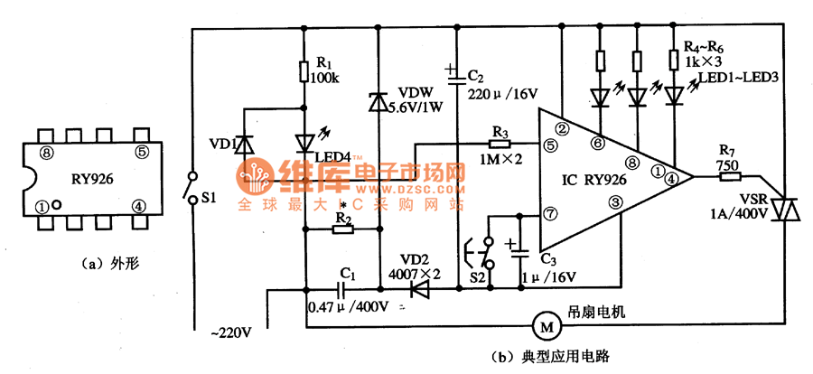
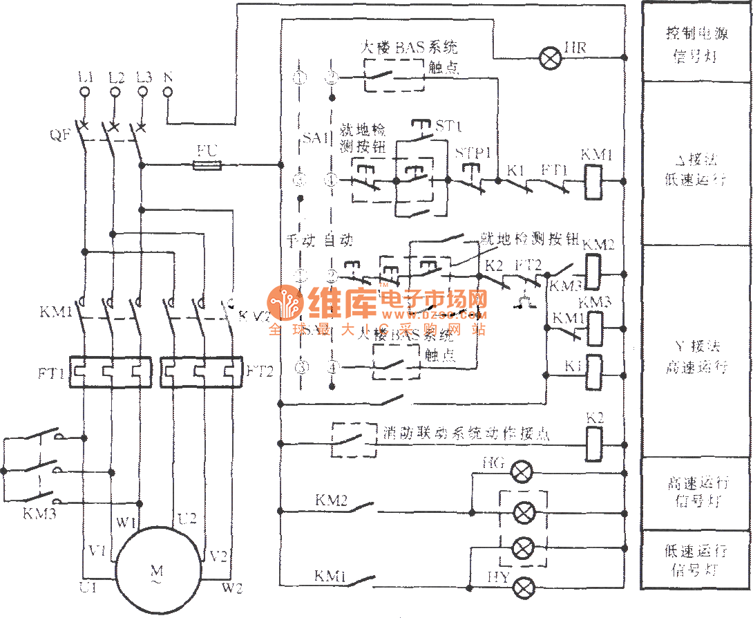
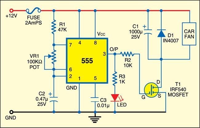
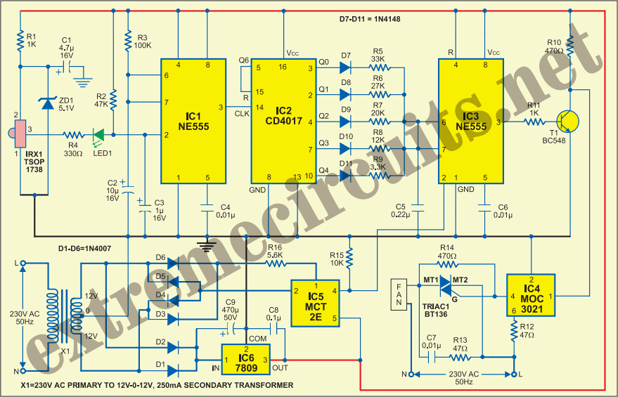
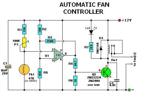
Fan control circuit diagram. This circuit is based on 555 timer. The key component of this temperature controlled fan circuit is thermistor which has been used to detect the rise in temperature. Below is the circuit diagram for temperature controlled dc fan using thermistor as temperature sensor. Tsop1738 is used in the circuit for sensing the infrared signal output from remote. Hi looking for a fan cooling circuit to cool 2 x fets on heatsinks in a 40w guitar amplifier i have 2 x 12v small bushless cooling fans 2 amplifiers to cool and 2 small 12v transformers as the amplifier rectified voltage is much higher and i also want the fans and the power for the fans independant from the amplifiers as much as possible so not to introduce noise. Er 1 2 4 5 diagram er4 diagram er7 diagram er6 diagram er5 3ø wiring diagrams 1ø wiring diagrams w2 orange brown blue black red grey w2 u2 u2 v2 v2 u1 u1 v1 v1 w1 w1 l1 l1 l2 l2 l3 l3 e e two speed motors high speed low speed orange brown blue black red grey m 1 m 1 l l n n e e 3 active wires plus.
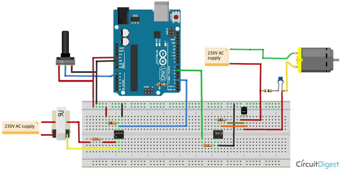
In this ceiling fan regulator circuit r1500kω is a variable resistor that is used to adjust the fan speedcapacitor c1 2a104j is a polyester film capacitor. The complete design for the proposed remote controlled fan dimmer circuit can be witnessed below. This is the simplest and reliable temperature control dc fan circuit on youtube with all the steps of making in depth. Breadboard and connecting wires circuit diagram. Pwm technique is used in controlling the speed of dc motor. Circuit diagram was included in the middle of this video.
Pin diagram of triact1 z0607. Dc fan motor power supply 5v. Jun 30 2020 explore juni joness board circuit diagram on pinterest. By using this pwm circuit you can control the speed of dc fan by moving the potentiometer variable resistance. See more ideas about circuit diagram circuit electronics circuit. The circuit discussed in this article eliminates the pwm idea for the fan dimming control instead employs few low power triacs for sequentially implementing the dimming or speeding effect on the connected fan motor.
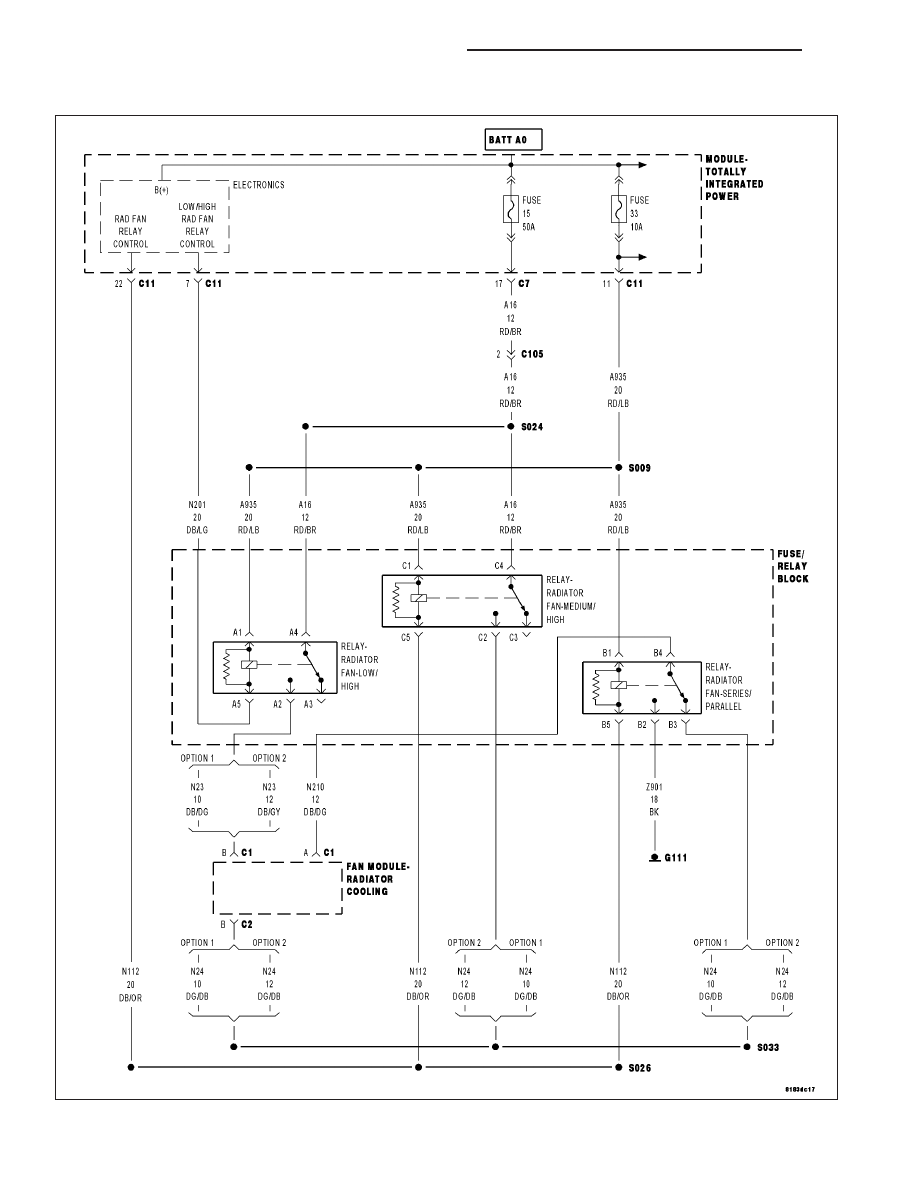
This home made wireless remote controlled switch system is a very easy to construct and can change our living experiance. This circuit can be. Dc fan speed regulator project. The circuit diagram of dc fan motor speed controller regulator circuit using 555. Ir infrared remote controlled switch circuit diagram for lightfan appliance. Cooling fans are now controlled by the ecm through the respective module network and using duty cycle control signals.
