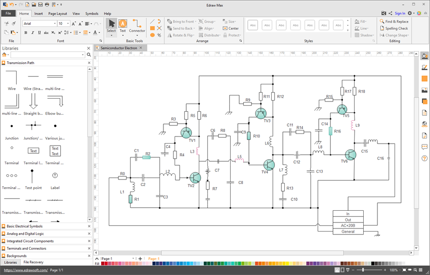
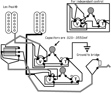
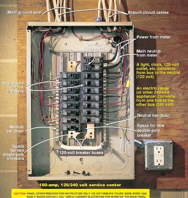
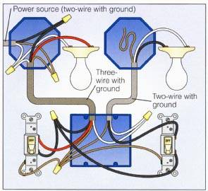
These diagrams show the functional apparatus at their appropriate relative physical locations. Lines are used to represent a single carrier multiple conductors installed in the same channel are shown as a single line with radial branches and the conductors.

Types Of Wiring Systems And Methods Of Electrical Wiring
Different types of electrical wiring diagram. Wiring diagrams help you identify wires and components as they are found on the equipment. Types of electrical diagrams or schematics. They are wiring schematic and pictorial diagrams. Wiring diagrams may also be referred to as connection diagrams. Different types of electrical diagrams and drawing. The uses of these two types of diagrams are compared in table 1.
The wiring diagram shows the interconnection wiring between the electrical equipment. Joint box or tee or jointing system. Once you understand the different types of switches and outlets and follow a wiring diagram you should be able to install a new electrical wiring in your home or repair existing problems with light switches and outlets. The two most commonly used are the wiring diagram and the schematic diagram. From the main switchboard various types of electrical loads such as fans lights room coolers and refrigerators are connected through the wiresthere are different types of wirings used for connecting the loads to the mains which can be used for house electrical wiring as well as industrial electrical wiring. Loop in or looping systemcasing and capping wiringbatten wiring cts or trslead sheathed wiringconduit wiringsurface conduit wiringconcealed conduit wiringtypes of conduitmetallic conduitnon metallic conduit.
Diagrams will show receptacles lighting interconnecting wire routes and electrical services within a home. Cleat wiring methods of electrical wiring systems wrt taking connection. There are three ways to show electrical circuits. What is electrical wiringdifferent types of electrical wiring systems. In electrical and electronics engineering we use different types of drawings or diagrams to represent a certain electrical system or circuitthese electrical circuits are represented by lines to represent wires and symbols or icons to represent electrical and electronic componentsit helps in better understanding the connection between. Within these articles you will find some of the most common questions homeowners ask about switches.
An electrical wiring diagram will use different symbols depending on the type but the components remain the same. Understands basic types of electrical drawings can produce a floor plan that displays understanding knows the difference between a circuit drawing and a wiring diagram draws and understands a wiring diagram extension activity draw more wiring diagrams that include more devices in different configurations. Wiring diagrams use electrical symbols like the ladder diagram but they try to show the actual locations of the components. Figure 8 large common electrical components.


