Jitender aug 17 2015 2. If the battery cannot last for 90 minutes it must.
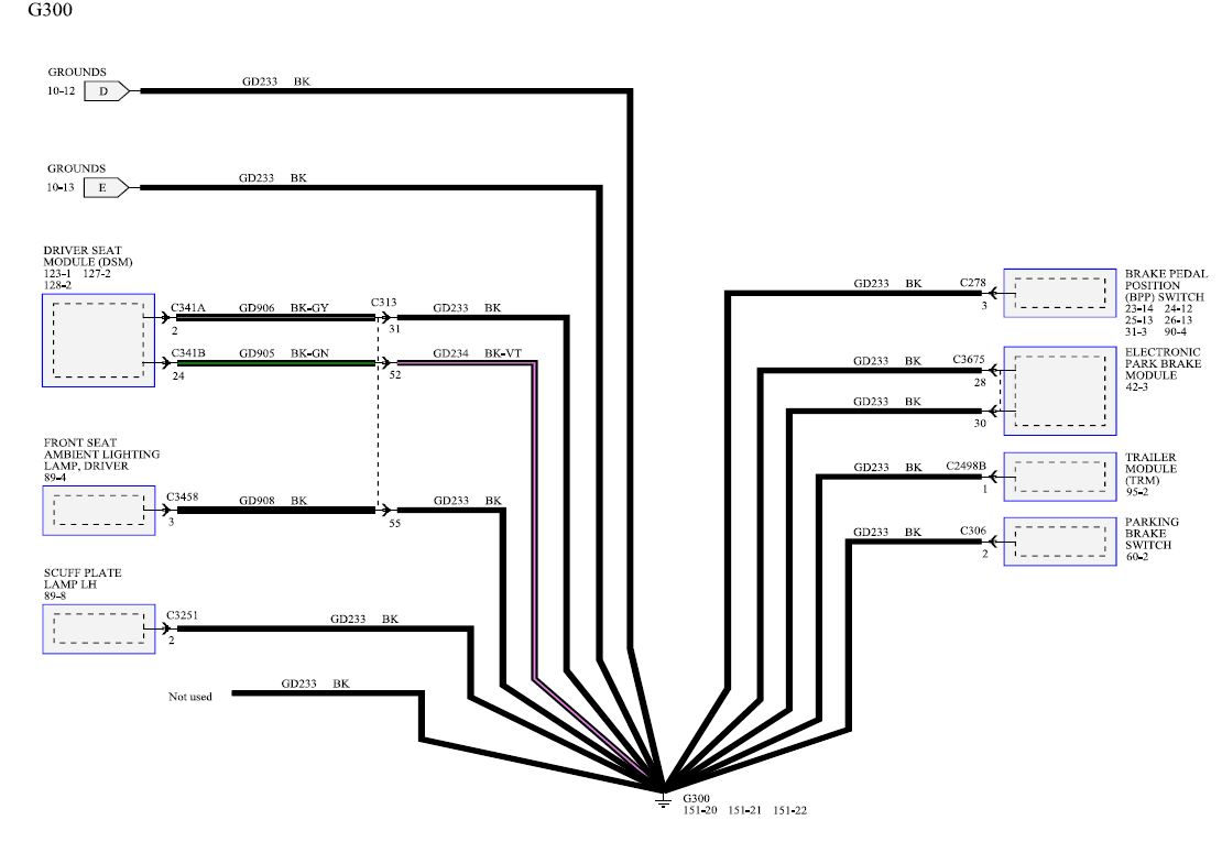
Brake Light Switch Wiring Diagram Ford F150 Forum
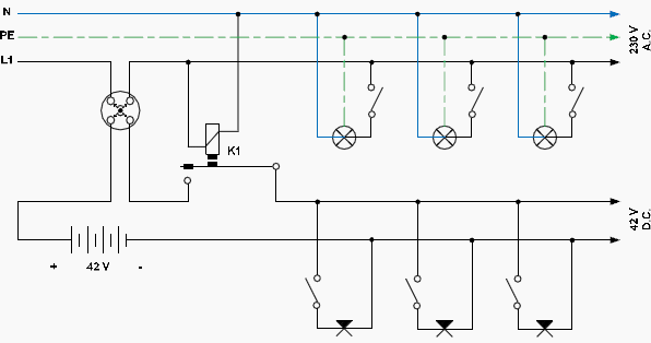
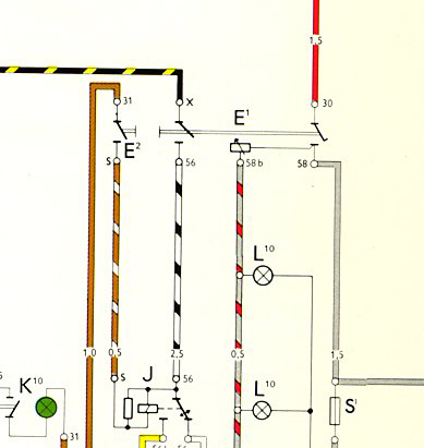
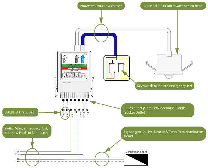
Emergency light switch wiring diagram. Emergency lighting test switch cat no. It took me a while to figure out what was what. Wiring diagram for maintained emergency light using key switch. Connect kitunit as per wiring diagram supplied. The emergency light test kits are designed to perform discharge test on. Circuit breaker q1 l1 l4 are not supplied.
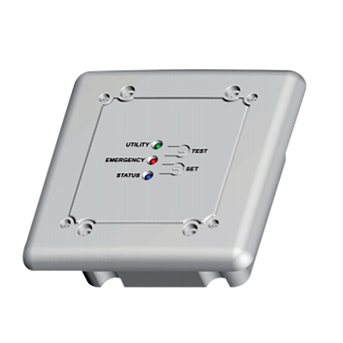
Harry highlights the problems with the old wiring system. Switch box test switch charge light black yellow yellow white unswitched switched or unswitched line common blk 120v white lamp ac emergency black white blue red blue bluewht redwht red yellow unit connector lpts charge indicator common ac. Ballast emergency ballast relay how to use the emergency ballast wiring guide. 682083 and 682084 this new emergency lighting test switch provides the option to add a power up time delay function used primarily in installations where discharge lamps are used. View attachment 9248. This diagram illustrates wiring for one switch to control 2 or more lights.
Whether the standard ballast is rapid start or instant start. Multiple light wiring diagram. Can someone confirm whether this diagram is ok for wiring up a maintained emergency light switch please. The hot and neutral terminals on each fixture are spliced with a pigtail to the circuit wires which then continue on to the next light. By operating the test switch on the new wiring system you are still simulating a mains failure its just the normal lighting is not extinguishing but the emergency lights are illuminating. A fully charged battery in good condition should power an emergency light for at least 90 minutes as mandated by ul underwriters laboratories.
3 position selector switch emergency lighting label green marker strip for marked circuits. Jitender screwfix select. This new feature is designed to avoid black out periods where emergency lights are turned off before discharge lamps. How many lamps the emergency ballast will light up if power fails usually one or two. Standard fluorescent ballasts have one wiring diagram. Jitender aug 17 2015 1.
Overview of emergency light fittings and using a key operated switch to disconnect power for test purposes. The source is at sw1 and 2 wire cable runs from there to the fixtures. Emergency ballasts have many wiring diagrams depending on the following.
