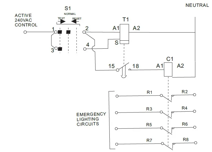
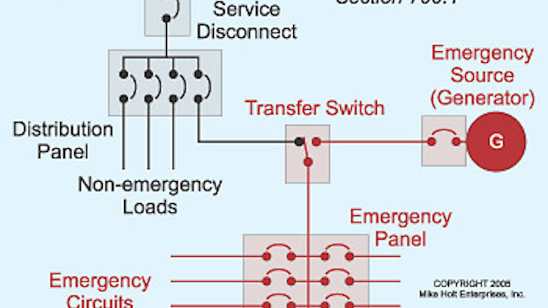
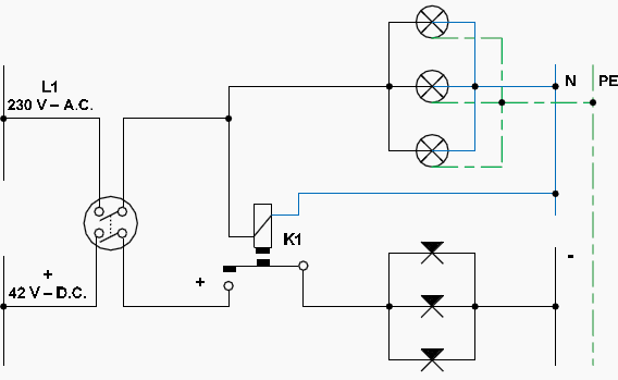
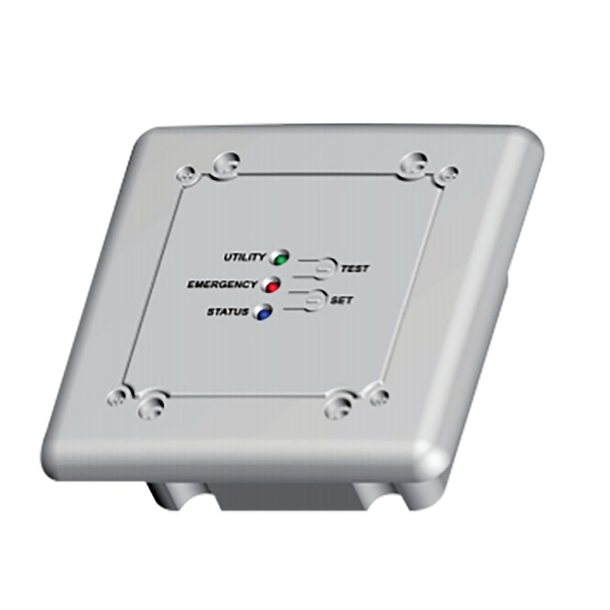
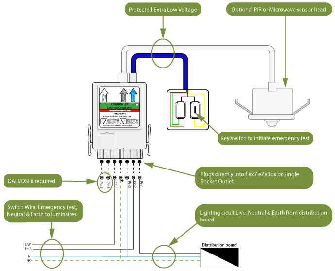
Ballast emergency ballast relay how to use the emergency ballast wiring guide. Wiring diagram for sensing and control of a large emergency lighting system.
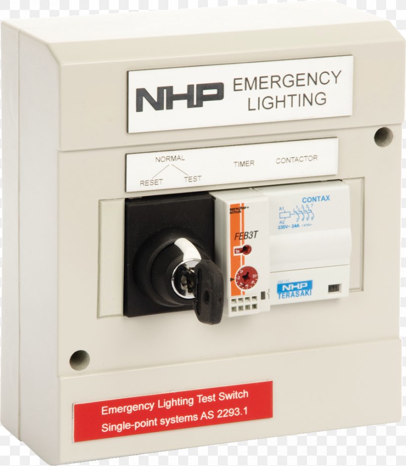
Emergency Lighting Wiring Diagram Electrical Wires Amp Cable
Emergency light test switch wiring diagram. Switch box test switch charge light black yellow yellow white unswitched switched or unswitched line common blk 120v white lamp ac emergency black white blue red blue bluewht redwht red yellow unit connector lpts charge indicator common ac. Recommended contactors to be used with the product include clipsal 4cnt11nc or hager esc227. 682083 and 682084 this new emergency lighting test switch provides the option to add a power up time delay function used primarily in installations where discharge lamps are used. A fully charged battery in good condition should power an emergency light for at least 90 minutes as mandated by ul underwriters laboratories. Operation engaging the selector switch to the test position will start the timer 2hrs. Harry highlights the problems with the old wiring system.
Emergency lighting test switch cat no. This new feature is designed to avoid black out periods where emergency lights are turned off before discharge lamps. Em test switch small system figure 2. Emergency light testing made easy what is emergency lighting test switch the nhp concept emergency lighting test switch kit allows quick and easy method to semi automate discharge testing of single point emergency lighting fittings in accordance with as nzs22931 and asnzs 22932 emergency evacuation lighting for buildings. Wiring diagram of the emergency test switch assembly. The emergency test switch uses a 1din size contactor not provided.
If the battery cannot last for 90 minutes it must. Self contained emergency luminaire with a manual test facility in the monitored supply typical single lighting circuit buildings. For a discharge test must be installed on both existing and new emergency lighting installationsthe multi 9 merlin gerin test kits are completely pre wired to provide an off the shelf solution to emergency light discharge test requirements. Wiring diagram for emergency operation at 120v 277v with 0 10v dimming emergency ballast and ac ballast must be fed from the same circuit easy installation product help tech help line call our experts 888 rab 1000 2012 rab lighting inc. By operating the test switch on the new wiring system you are still simulating a mains failure its just the normal lighting is not extinguishing but the emergency lights are illuminating.


