The term can be used to mean an engine control unit or an electronic control unit both are control units but one denotes the specific use in an engine system. It consists of a battery ignition switch electronic control unit magnetic pick up reluctor or armature ignition coil distributor and spark plugs.

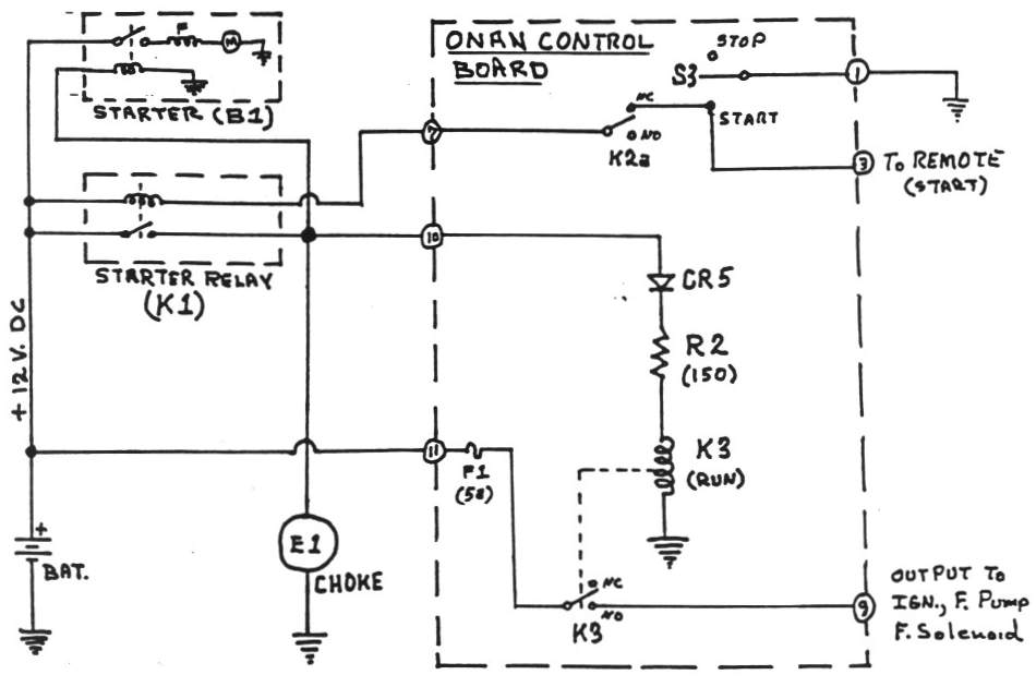
Ac Motor Control Circuits Worksheet Ac Electric Circuits
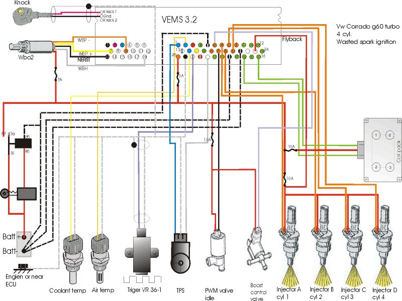
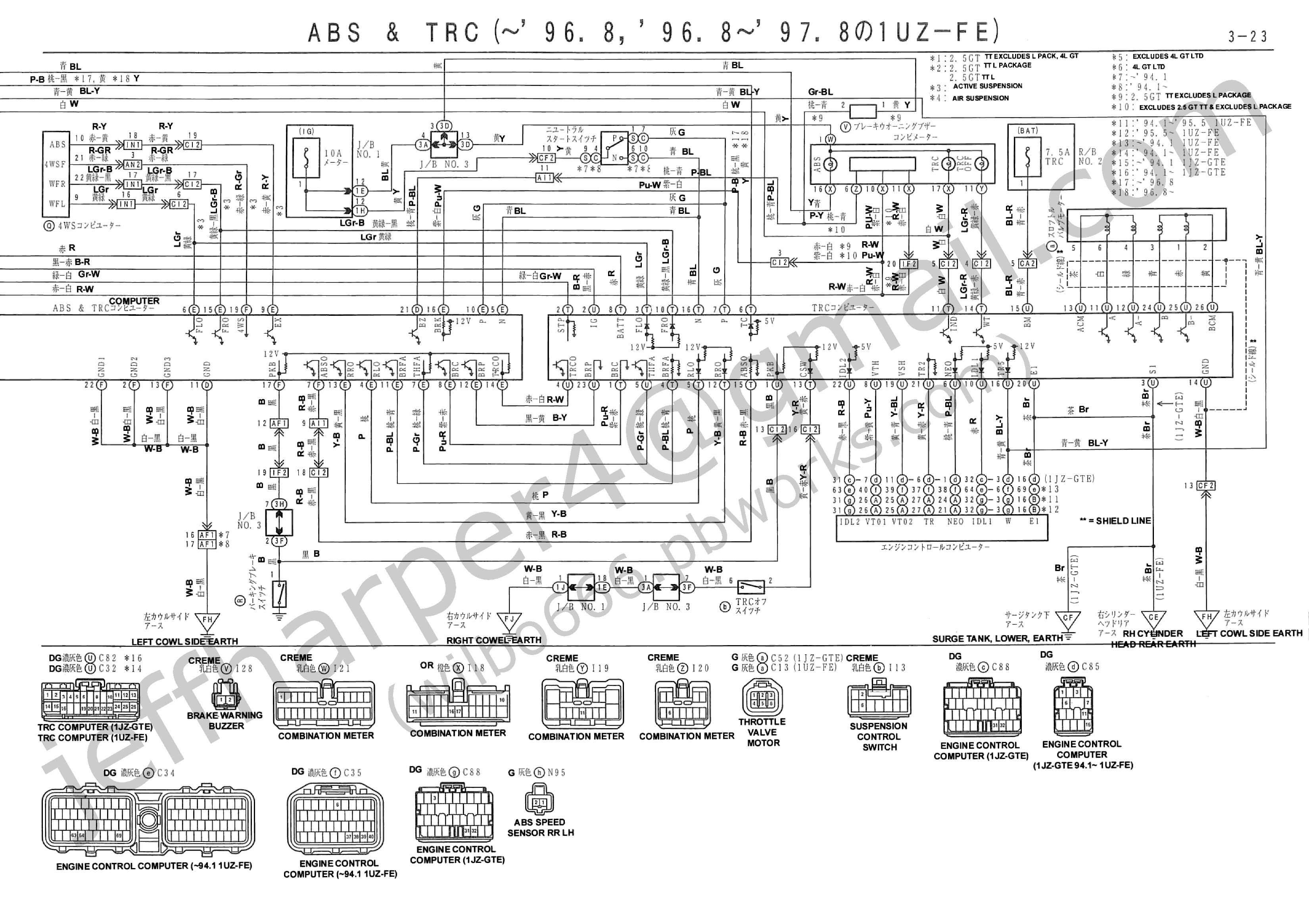
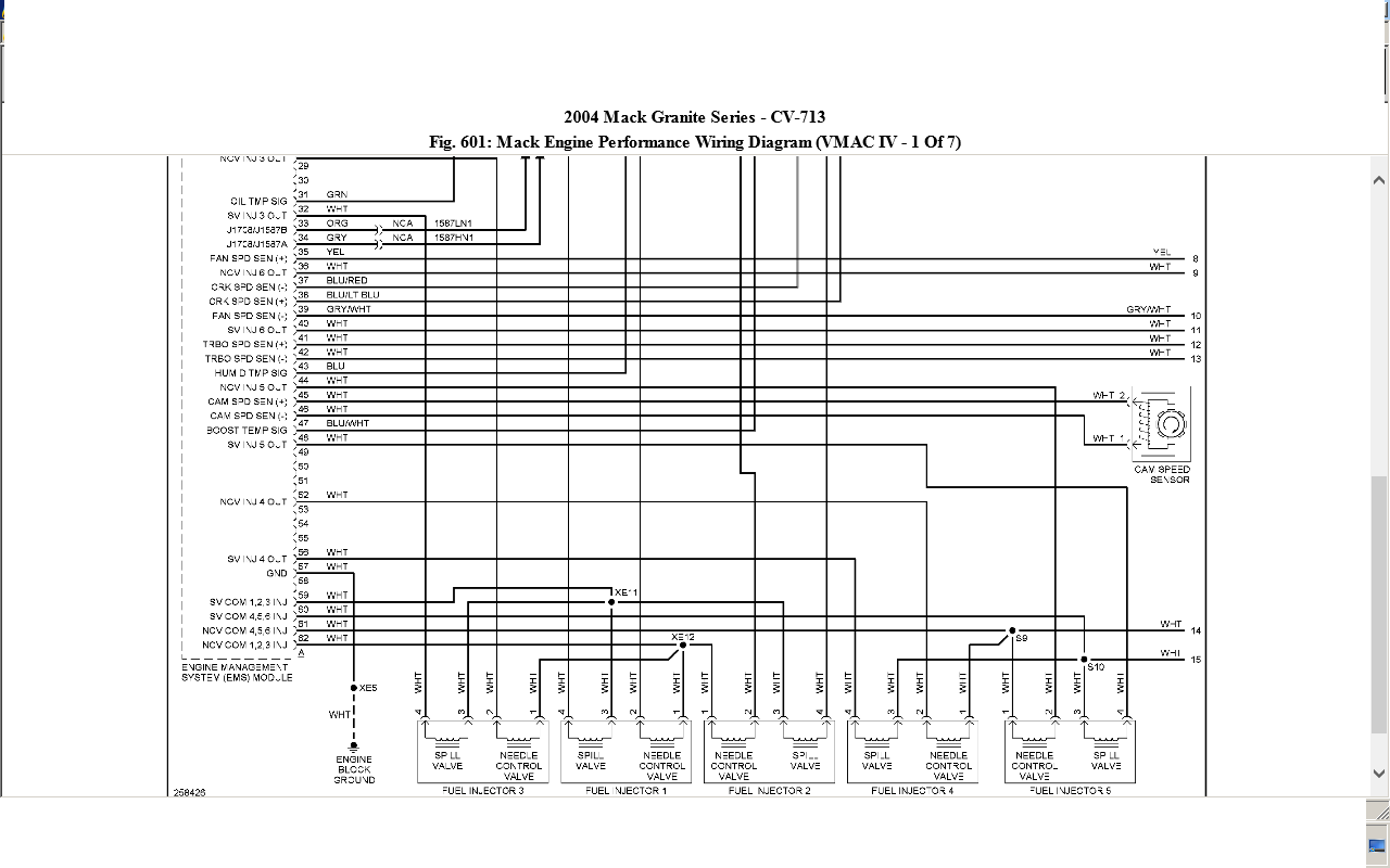
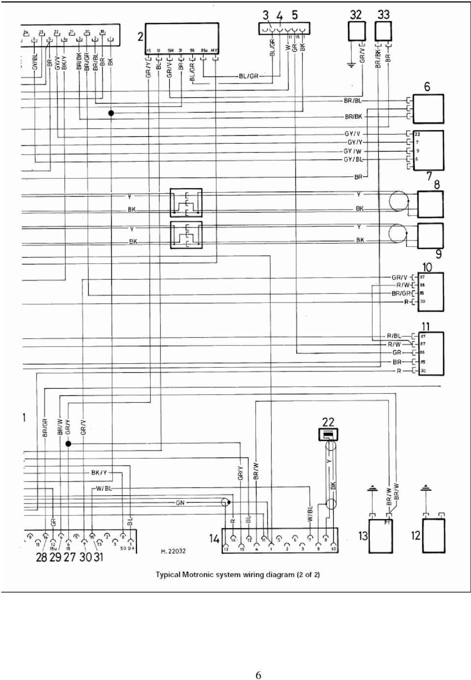
Electronic control unit circuit diagram pdf. Figure 1shows a simple schematic diagram of a power sup ply. Delivery pipe fuel pressure is maintained constant by a fuel pressure regulator opening and closing times of between 05 and 1 ms. An engine control unit ecu also commonly called an engine control module ecm is a type of electronic control unit that controls a series of actuators on an internal combustion engine to ensure optimal engine performance. Ecuelectronic control unit and its mount location 5. Design of electronic control unit ecu for automobiles electronic engine management system m. Engine control unit diagram toyota 1kz 15 pdf drive search and download pdf files for free.
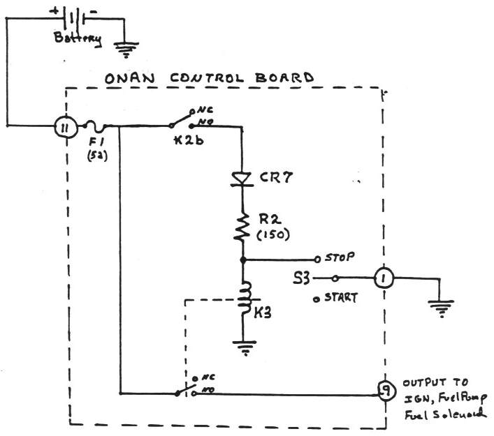
A schematic diagram of an electronic ignition system is shown in figure 236. It does this by reading values from a multitude of sensors within the engine bay interpreting the data using multidimensional performance maps called lookup tables. There is a fixed drive ratio of. Components of ecu an ecu consists of a number of functional blocks. Here is a simple circuit to control the temperature of a soldering. Circuit diagram help from this book.
On the original 4m e efi engine primary circuit current flow is controlled by an igniter. On it you can see some of the conventions used. Electronic fuel injection efi allows precise and fast control of fuel injected by control of the zon time period of the solenoid operated injectors spray nozzle and plunger. Heat control unit 101. Also complete explanation for the function of an ecu and its history. Explanation for the term ecu in the automotive context.
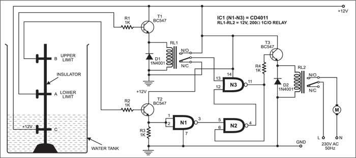
Types of ecu ecm engine control module ebcm electronic brake control module pcm powertrain control module vcm vehicle control module bcm body control module 6. Shows position of the electronic control unit relays relay block etc this section is. Construction methods of electrical and electronic circuits. Give your feedback by mailing me. Figure 2 shows the symbols for such basic components as wires and understanding and using electronic diagrams. Electronic charging and engine starting circuit diagram there could be third harmonic3f at the neutral point.
Construction of electronic ignition system. Project first stage report ee 696. Hardware design of ecu 7.
