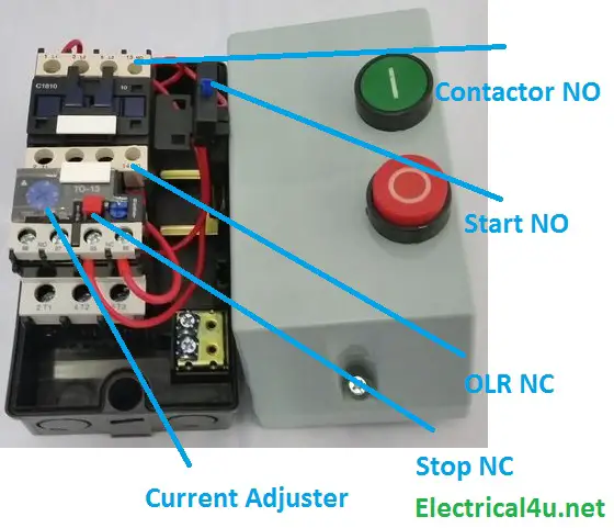
It reveals the elements of the circuit as simplified forms and also the power and signal links between the gadgets. The below wiring diagram shows how we would assemble a complete motor starter with a startstop button for a single phase motor utilizing a 3 pole contactor.

Diagram 3 Wire Motor Control Wiring Diagram
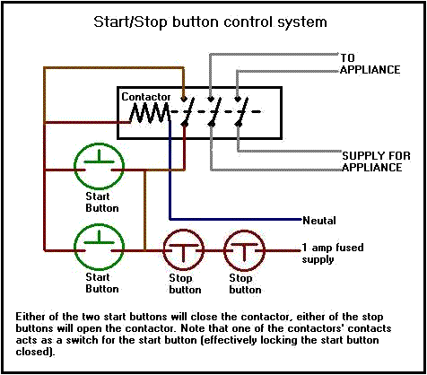
Stop start contactor diagram. Start stop buttons. Contactors and relays explanation. Note that one one of the contactor acts as a switch for the start button. Depressing the stop button breaks the circuit de energizing. Collection of 3 phase contactor wiring diagram start stop. Pete vree 45130 views.
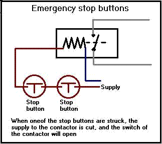
These lines far exceed the 120 volts ac standard in most homes. How a contactor can be used to provide emergency stop and nvr functions for a motor or other device. Many large pieces of equipment are powered directly from high voltage lines. When you press the start button and the stop button is not pressed the 24vdc relay energizes and it pulls in the r1 contactor that feeds three phase power to the motor. 240 volts ac and 480 volts ac are commonly used for these large pieces of. The start and stop circuits could alternatively be controlled using a plc.
The most common use of 3 wire control is a startstop control. Basiclly you press start button which powers the coil which then pulls in the contactor once the contactor makes the feed from the stop button holds the coil in untill the stop button is pressed which breaks the circuit. As always feel free to contact us with any questions. See image below for an example of 3 wire control being used to pull in a contactor to start a 3 phase motor. I zl ii i i ii i i fo 0. We hope this helps further your understanding of motor controls.
1 j start 2 3 stop i no. Start stop control wiring diagrams single station basic circuit r 1 klai. Ladder diagram basics 3 2 wire 3 wire motor control circuit. Ladder diagram basics 3a nema contactor overview duration. I operation depressing the start button energizes coil m hold in contacts m and maintains the circuit after the start button is released. A wiring diagram is a simplified traditional pictorial depiction of an electric circuit.
How to wire a contactor. This diagram is for single phase motor control. It uses a contactor an overload relay one auxiliary contact block a normally open start pushbutton a normally closed stop pushbutton and a power supply with a fuse. A simple circuit diagram either of the two start buttons will close the contactor either of the stop buttons will open the contactor.


