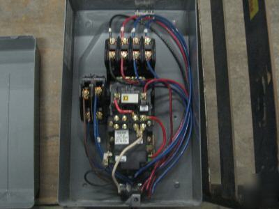
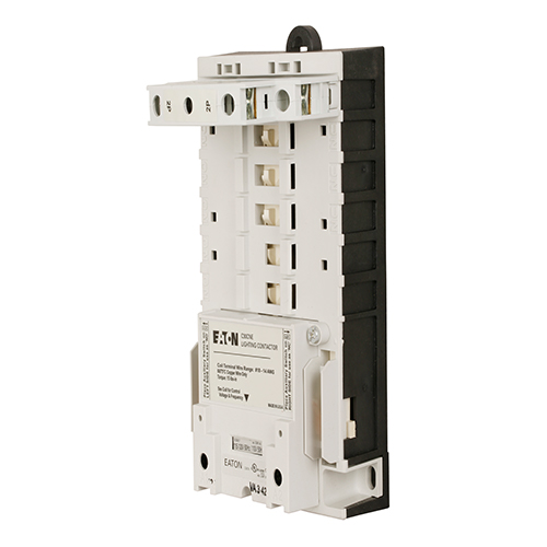
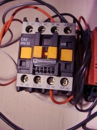
Figure 6 auxiliary contact assembly layout 2. Most lighting and heating applications require a contactor to control the loads.

4 Pole Lighting Contactor Wiring Diagram C3 Wiring Diagram
Electrically held contactor wiring diagram. Mechanically held lighting contactor wiring diagram collections of mechanically held lighting contactor wiring diagram download. One type of contactor is an electrically held contactor which is similar to a magnetic starter. Electrically held to mechanical latch contactor retrofit instructions 5 1502 in001 en p xqh install the mechanically latched auxiliary contact assembly 1. Lighting contactor wiring diagram withtocell 1400 771 with cell. To order type 4x. 6 6 for mechanically held contactor re install the control module and cover.
5 for electrically held re install coil assembly and cover. Mechanically held lighting contactor wiring diagram download. 2 wire and 3 wire control wiring options 2 wire control standard table 5 4. 7 7 operate the contactor manually using manual operating tabs on the side. Wire the closing and trip coils to the mechanically latched auxiliary contact assembly as shown in the diagram below. Mechanically held lighting contactor wiring diagram download.
Check that the latch and latch cover at the bottom are still properly installed. 8903la1000v81cff4t contactor type l multipole lighting electrically held 30a 10 pole 600 v 110120 vac 5060 hz coil nema 3r12 buy online view details. The mechanically held contactor must. Class ecc03 non combination electrically held lighting contactor 2 or 3 wire control these are the catalog numbers for type 4x 304 grade stainless steel as indicated by the seventh digit 4. Electrically held contactors siemens contactor type clm.


