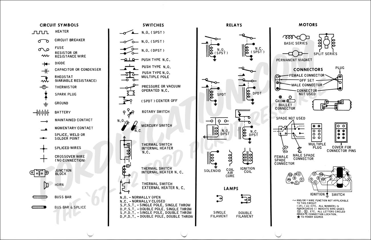
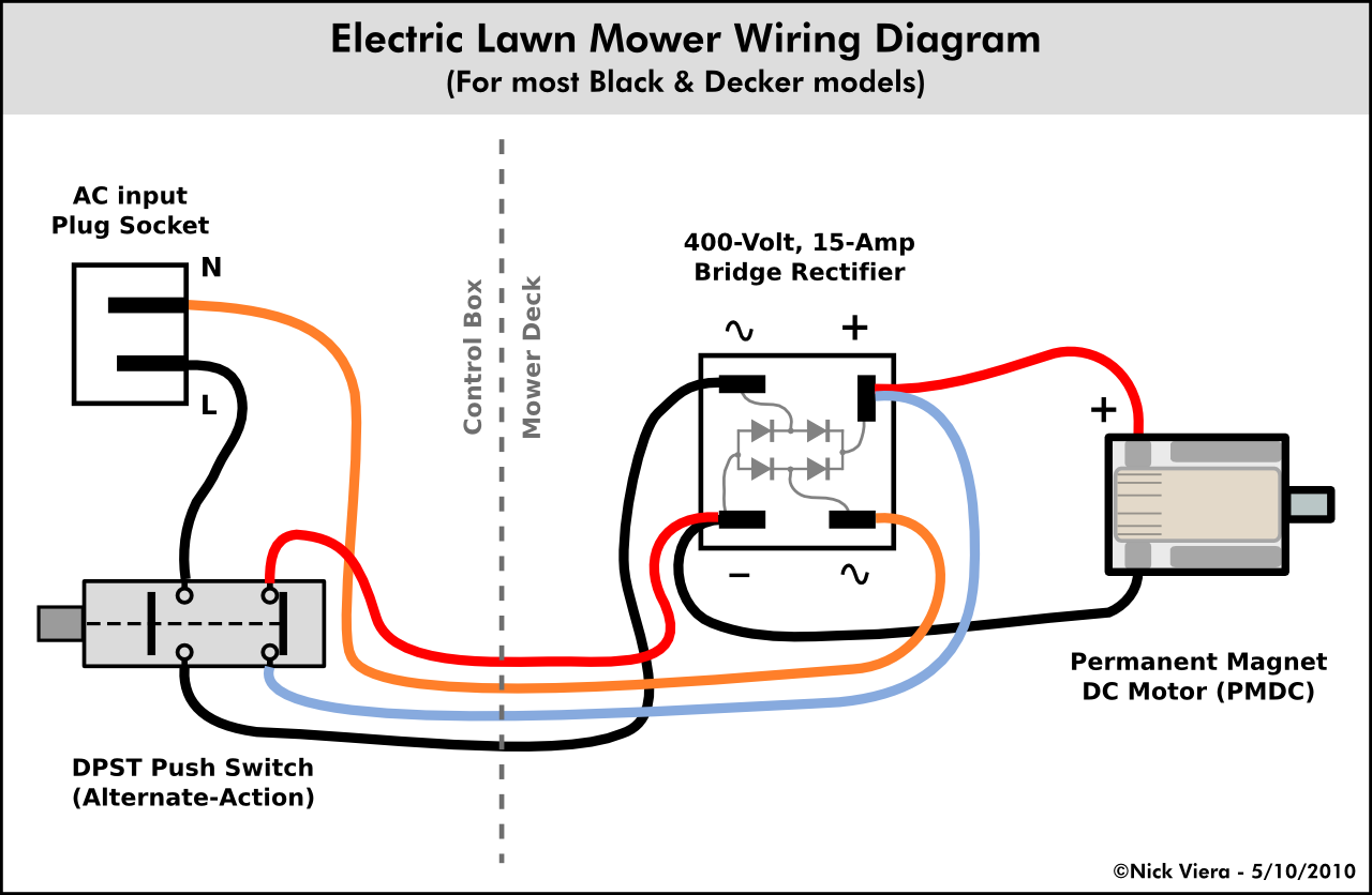
The electrical symbols will not only show where something is to be installed but what type of device is being installed. When looking at any switch diagram start by familiarizing yourself with the symbols that are being used.
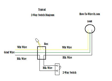
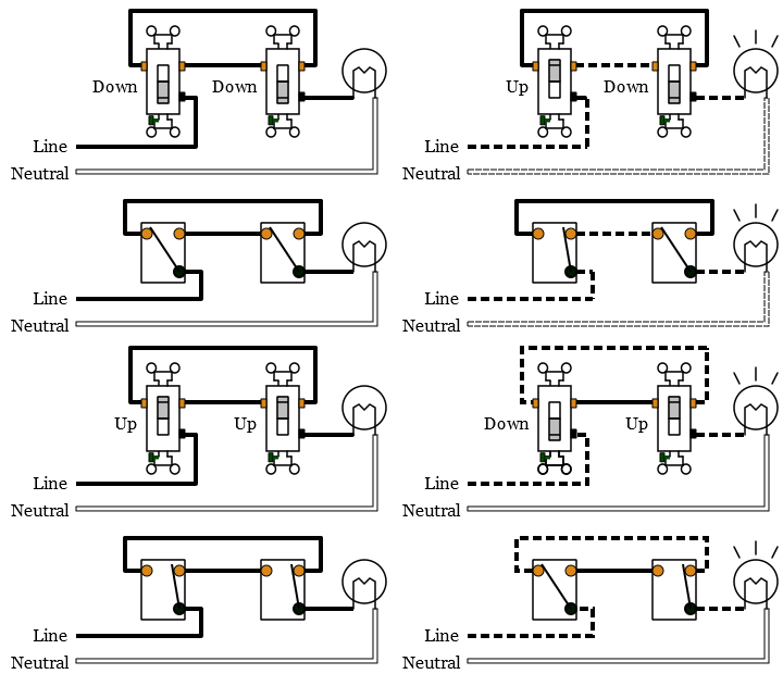
Wiring A 2 Way Switch
What is electrical wiring diagram. When installing a subpanel for the garage the first thing to do is to calculate the expected load. See more ideas about electrical wiring diagram electrical wiring diagram. Wiring connections in switch outlet and light boxes. That said for specific situations there are industrial standards with different connectors and wire arrangements. Electrical wiring of the distribution board with rcd single phase from energy meter to the main distribution board fuse board connection. Room air cooler wiring diagram 2.
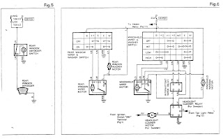
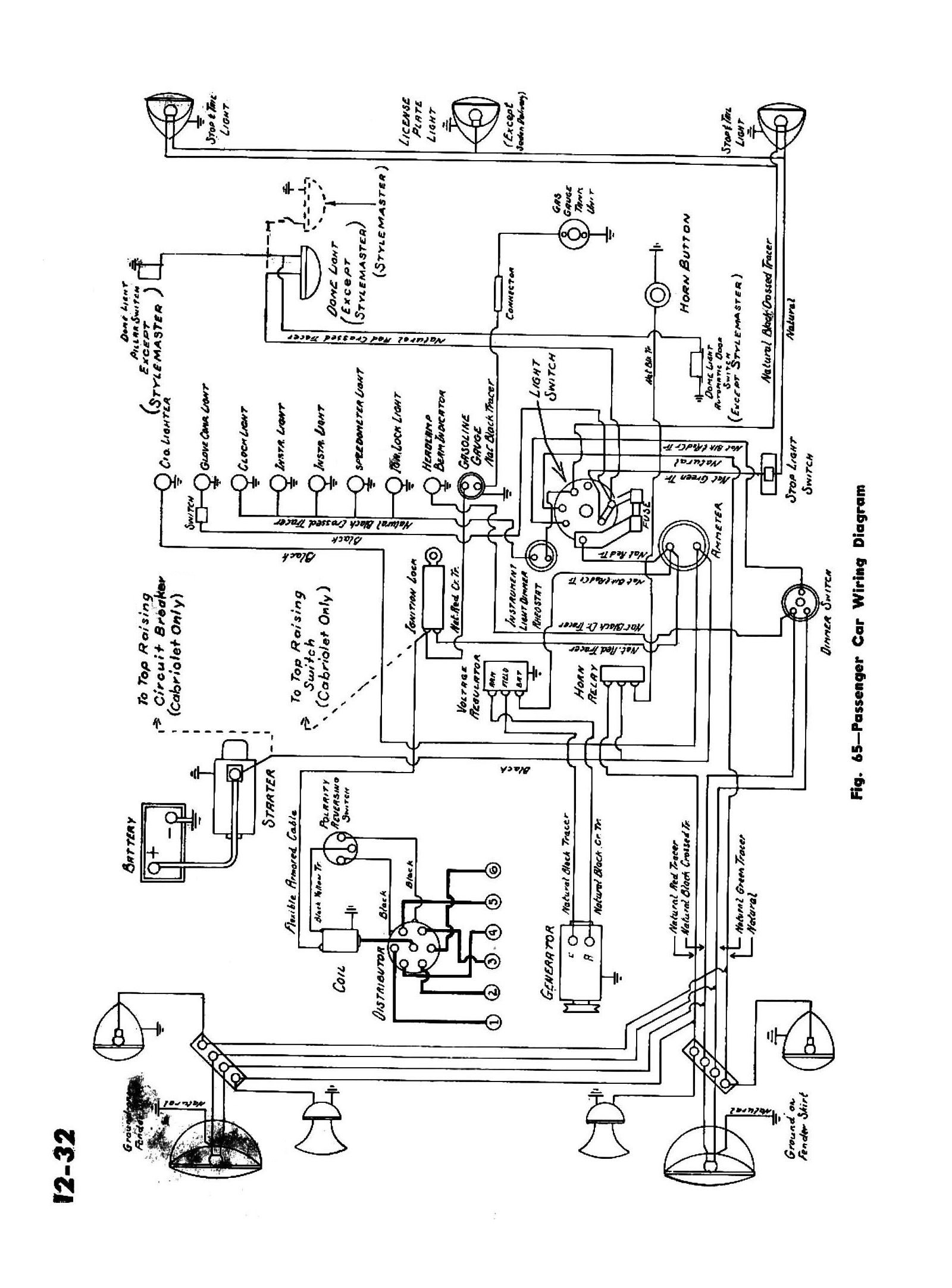
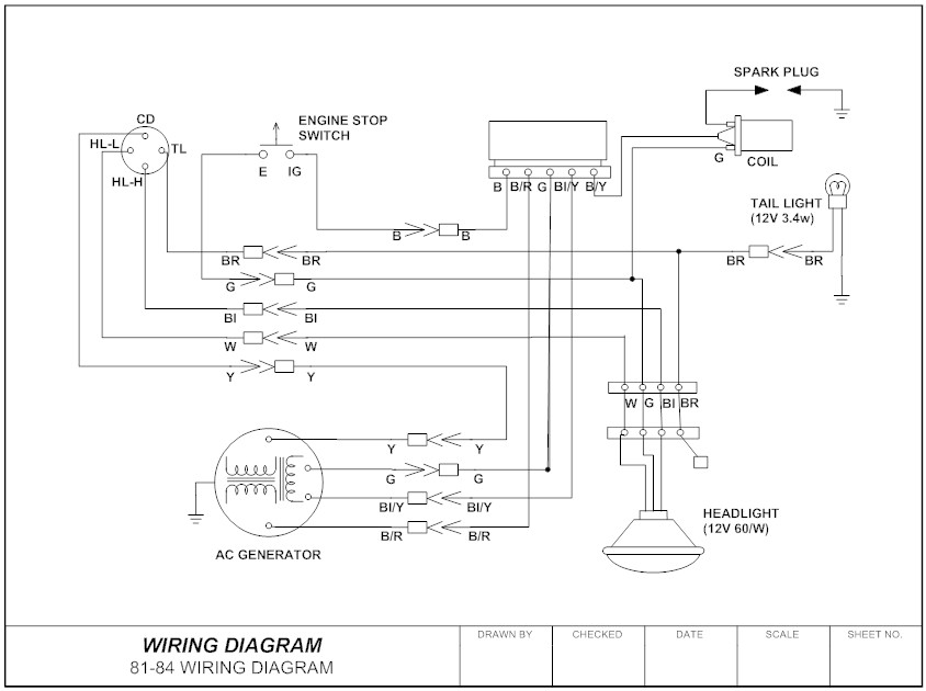
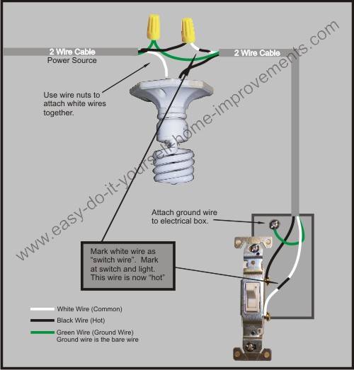
A wiring diagram usually gives information about the relative position and arrangement of devices and terminals on the devices to help in building or servicing the device. The following house electrical wiring diagrams will show almost all the kinds of electrical wiring connections that serve the functions you need at a variety of outlet light and switch boxes. Apr 14 2019 explore 101warrens board electrical wiring diagram followed by 4307 people on pinterest. House electrical wiring diagrams. This determines the size of the panel and the amperage rating of the circuit breaker that controls it. Room air cooler electrical wiring diagram 1.
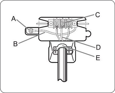
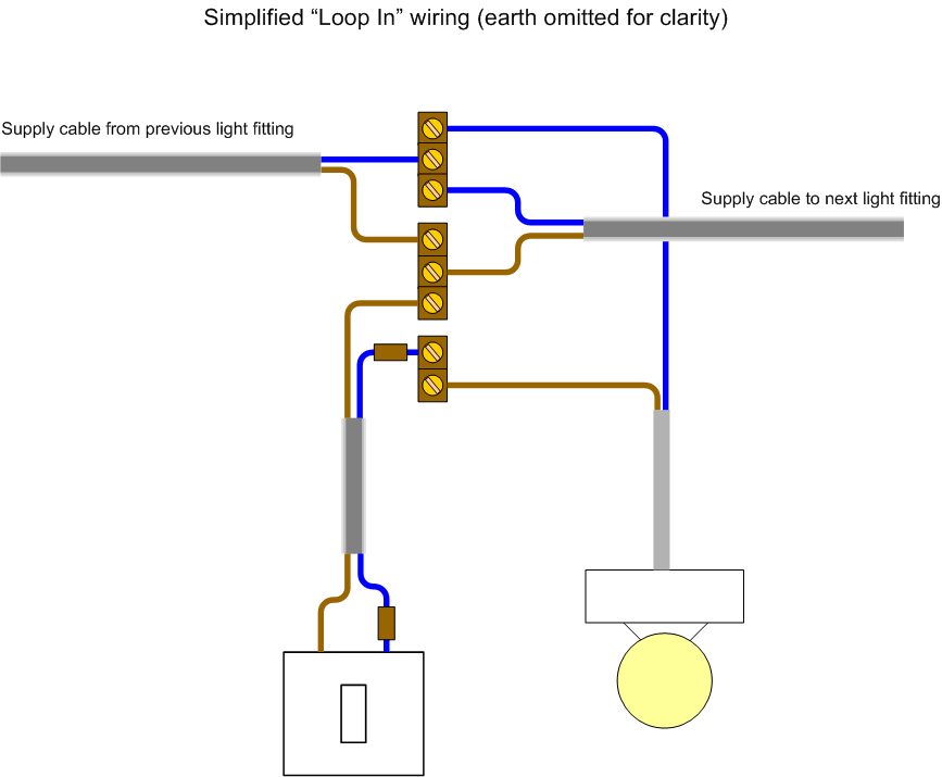
It shows how the electrical wires are interconnected and can also show where fixtures and components may be connected to the system. It gives you over 200 diagrams. A wiring diagram is a simplified conventional pictorial representation of an electrical circuit. Other electrical diagram types. Block diagrams often used for higher level less detailed descriptions for understanding overall concepts use the same. It shows the components of the circuit as simplified shapes and the power and signal connections between the devices.
Wiring diagrams function very much the same way but employ a different set of symbols. We recommend these standards because they are pretty universal. With capacitor marking and installation single phase electrical wiring installation in home according to nec iec. The following trailer wiring diagrams and explanations are a cross between an electrical schematic and wiring on a trailer. A wiring diagram is a simple visual representation of the physical connections and physical layout of an electrical system or circuit. Click more in the symbol library drop down menu and there are even more electrical symbols to choose from.


