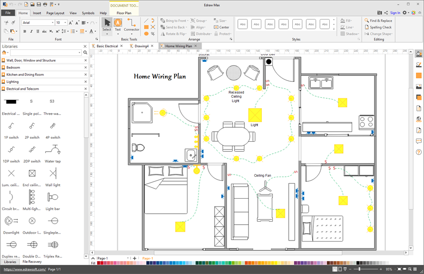
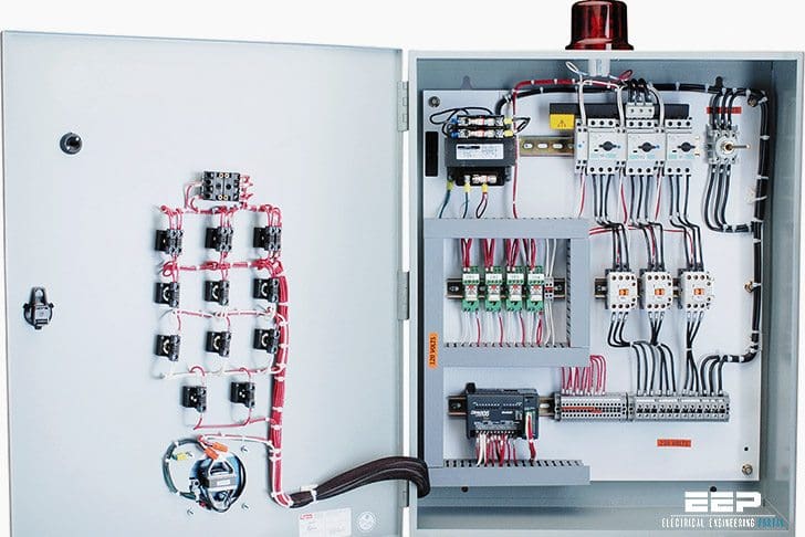
These tags can be found in the panel as well. It reveals the components of the circuit as streamlined shapes and the power and also signal connections in between the tools.
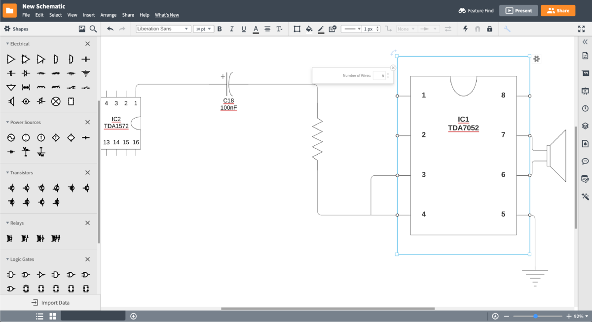
Circuit Diagram Maker Lucidchart
How to read control panel wiring diagram pdf. Basics 17 tray conduit layout drawing. Phase 1 l2 l4. Assortment of plc control panel wiring diagram pdf. Phase 2 l1 l2 l3 ground when used. When including a plc in the ladder diagram still remains. This is what we draw using autocad electrical.
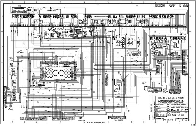
This current track layout simplifies the wiring diagram. The power supply is shown at the top and the earth at the bottom to facilitate understanding of the current flow. Each of the wires in the wiring diagram has a tag number. Basics 16 wiring or connection diagram. Each page of the wiring diagram shows the exact wiring for different sections of the control panel. A diagram that uses lines to represent the wires and symbols to represent components.
Basics 18 embedded conduit drawing. Basics 12 12 208 vac panel diagram. Electrical control panel wiring diagram pdf download diesel generator control panel wiring diagram. A wiring diagram is a streamlined conventional pictorial depiction of an electrical circuit. Centralrelay panel the centralrelay panel is indicated in gray at the top of the wiring diagram page. Refer to the example on page 3 for the basic layout of the wiring diagram.
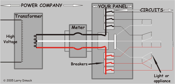
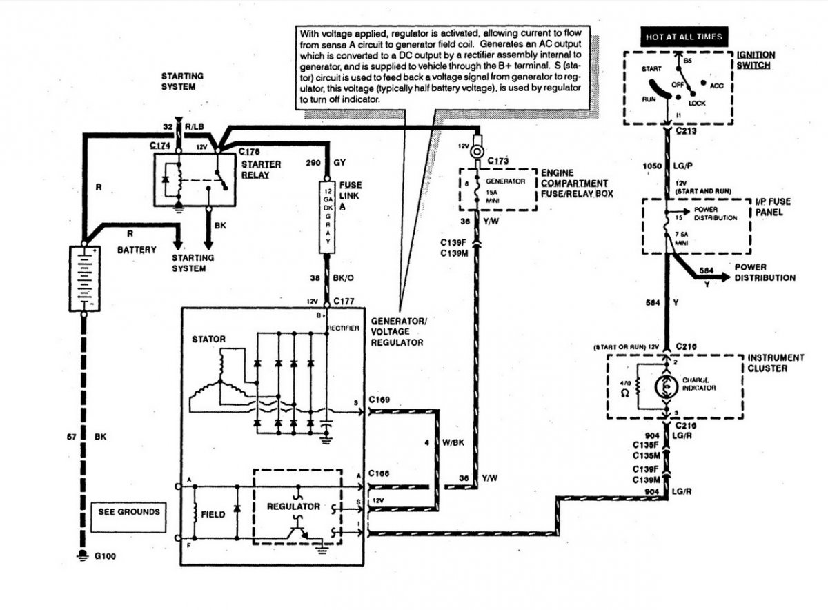
All the wiring that you see in the panel is done based on the wiring diagram. For example a property builder will want to read the physical location of electrical outlets and light fixtures by using a wiring diagram to prevent costly mistakes and building code violations. A 4 how to read the wiring diagrams how to read circuit diagrams how to read circuit diagrams the circuit of each system from fuse or fusible link to earth is shown. Basics 14 aov schematic with block included basics 15 wiring or connection diagram. Conductor symbols crossing where they do not connect is kept to a minimum. Electric motor drawing at getdrawings.
Basics 13 valve limit switch legend. Typical controller markings typical elementary diagram iec typical controller markings typical elementary diagram table 4 control and power connections for across the line starters 600 v or less from nema standard ics 2 321a60 1 phase 2 phase 4 wire 3 phase line markings l1 l2 l1 l3. This figure shows the e stop wired to cutoff power to all of the devices in the circuit including the plc. Figure 5 below shows a schematic diagram for a plc based motor control system similar to the previous motor control example. But it does tend to become more complex. Basics 19 instrument loop diagram.
Electrician circuit drawings and wiring diagrams youth explore trades skills 3 pictorial diagram. A diagram that represents the elements of a system using abstract graphic drawings or realistic pictures.


