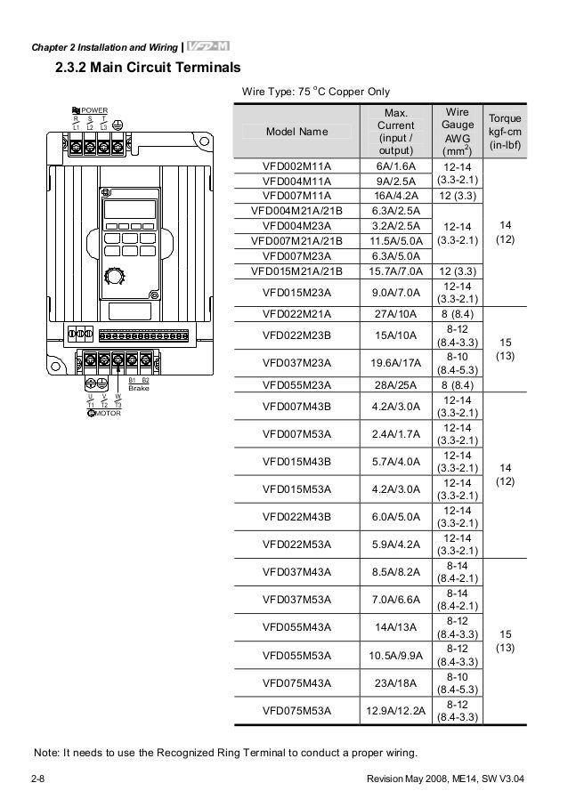
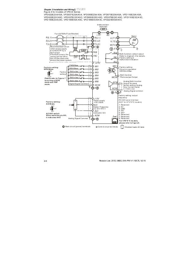
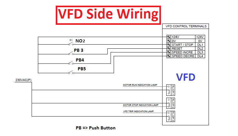
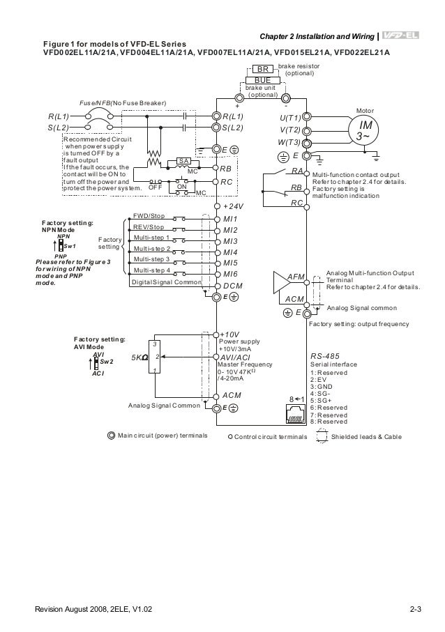
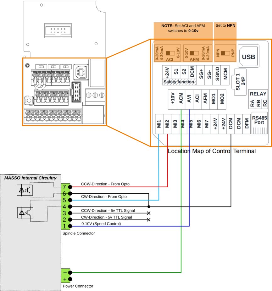
The grounding method must comply with the laws of the country where the ac motor drive is to be installed. All rights reserved 31 basic wiring diagram for wiring of the inverter it is divided into the main circuit and the control circuit.

Of 8258 Delta Vfd Control Wiring Diagram Download Diagram
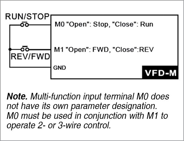
Delta vfd wiring diagram. I am here with giving you a vfd start stop wiring diagram for running a vfd through panel board push button and keypad of the vfd it is called hmi. For programming the vfd m. 1 the vfds three phase ac input terminals rl1 sl2 tl3 the power lines input terminals connect to 3 phase ac power through line protection or leakage protection breaker it does not need to consider the connection of phase sequence. We strongly recommend using a certified electrician to set up your vfds. Learn the basic wiring of variable frequency drives vfd with our electrician steve quist. T1 t2 t3 used for giving 3 phase input to vfd and connecting motor to it and wires coming out of m0 m1 and gnd.
Vfd m d series is used only to control variable speed of 3 phase induction motors not for 1 phase motors or other purpose. Find specifications manuals ordering information and compatible accessories here. Page 5 vfd m d series is the specific drive for the elevator door and other automatic door control not for those devices that may cause personal injury such as life support equipment. Its supposed to assist all of the average user in developing a proper method. Switch on the 3 phase power supply. Delta ms300 vfd2a8ms21ansaa 05 hp 1 ph 28amps 208240 volts ac input.
Main circuit wiring the vfd main circuit terminals shown as below figure. Vfd v series 3 2 delta electronics inc. Vfd start stop wiring diagram. Vfd is a short form of variable frequency drive or variable voltage variable frequency drivethe vfds are working based on changing the input frequency and input voltage of the motor we can change the speed of the. In this video we used the very popular mitsubishi d700 series vfd showing single phase and three phase wiring instructions. Ground the vfd el using the ground terminal.
Controlling a digital keypad on delta vfd m steps for complete motor control. Wiring diagram vfd bypassstar delta starter schematic at discrd vfd wiring diagram. Refer to the basic wiring diagram. Vfd el series is used only to control variable speed of 3 phase induction motors not for 1 phase motors or other purpose. Pin out connection diagram for vfd m fig. Check connections of l1 l2 l3.
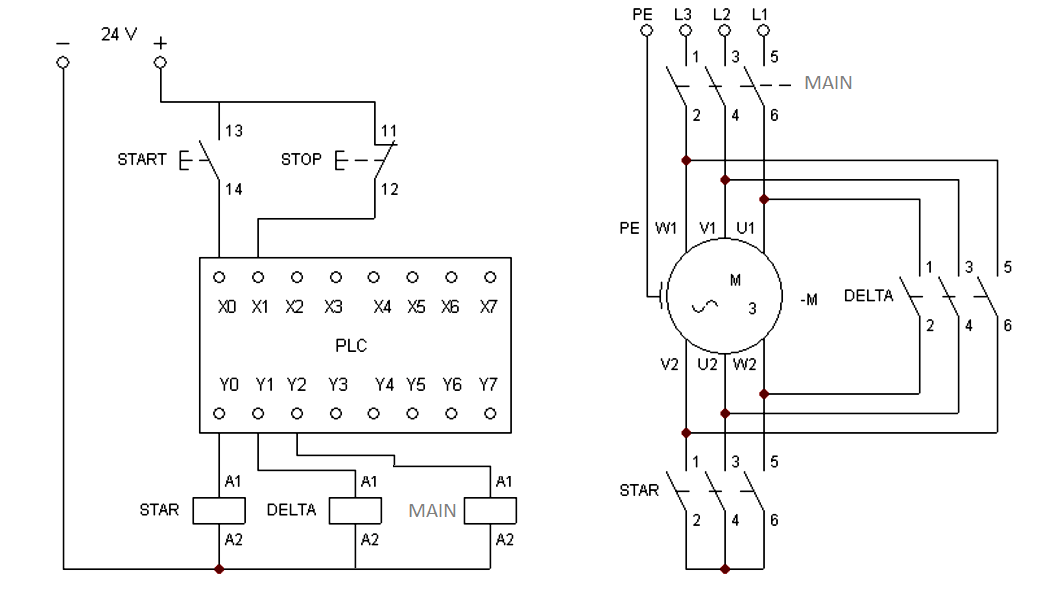
Wiring diagram will come with a number of easy to follow wiring diagram guidelines. Star delta connection without motor use incandescent light bulb star delta. These directions will likely be easy to understand and implement. Acdc drivevfd control terminal wiring diagram and concept हद म a for automation. The vfds showed in the video are the d720s 230v single phase and the d720 230v three phase. Refer to the basic wiring diagram.
Users could open the case cover and could inspect the main circuit terminal and the control circuit.


