Episode 22 how to bend conduit 12 34 and 1 emt bending 90s offsets box offsets kicks duration. It can be observed that at point a kcl is satisfied.
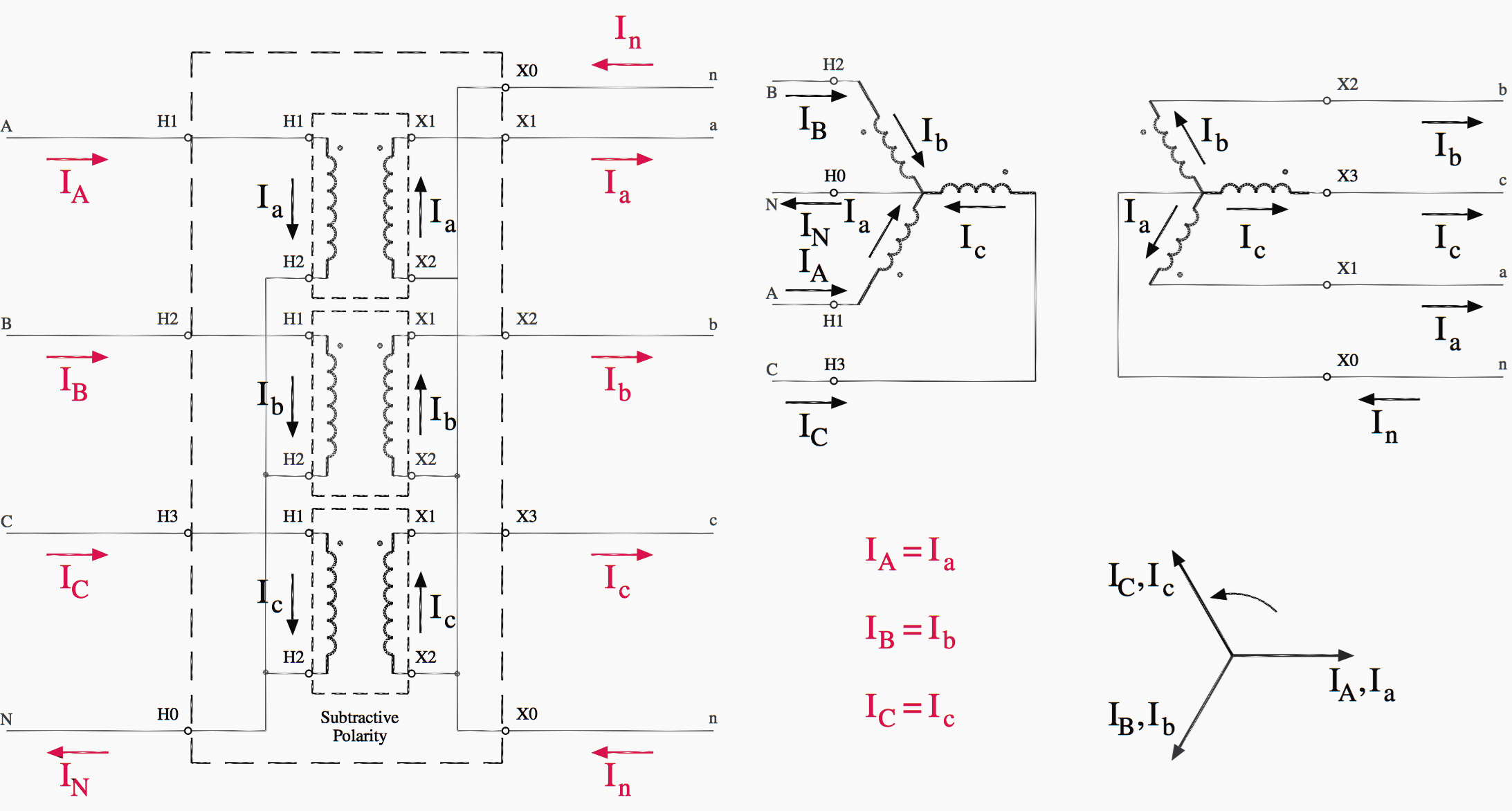
0eda3 Potential Transformer Three Phase Wiring Diagram
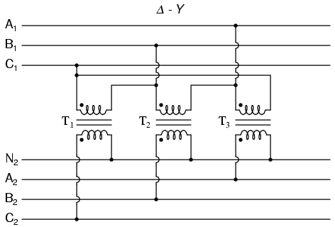
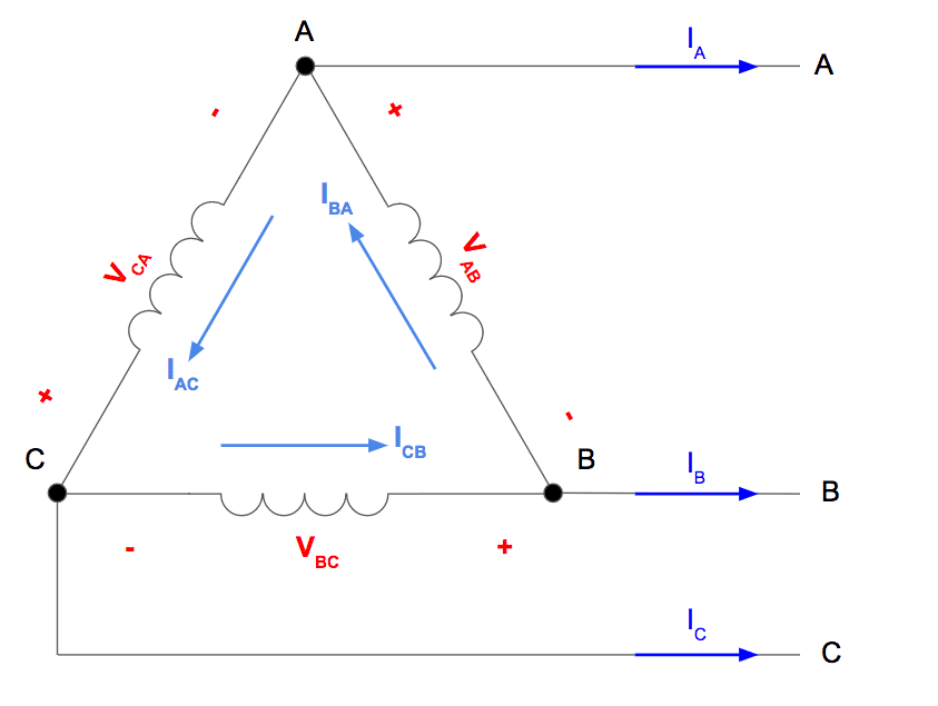
Delta delta transformer wiring diagram. Take close notice of the polarity for each winding in the figure below. Electrician u 554864 views. The three single phase transformer implementation can be seen by disregarding the outer dashed outline and the bushing labels. A four wire delta 4wd electrical service is a three phase delta service with a center tap on one of the transformer windings to create a neutral for single phase loads. The dashed lines indicate the transformer outlines. Each transformer is rated as 10 kva current rating is 10 a and voltage rating is 1000 v.
Also recall that phase difference between line current and line line voltage phase to phase voltage is 30 the same is reflected in the. 1 3 i l of the line current where i l is the line current. Motors loads are commonly connected to phases a b and c while single phase loads are connected to either phase a or c and to neutral. Connection diagram of open delta transformer. One disadvantage of delta connected three phase transformers is that each transformer must be wound for the full line voltage in our example above 100v and for. This video explains the correct and proper wiring of open delta open delta transformer banks.
Another configuration is known as the delta for its geometric resemblance to the greek letter of the same name δ. Disadvantages of delta delta transformer connection. The above figure shows the connection diagram of an open delta system. A free training video from northwest lineman college wwwlinemanedu. In a delta connected dd group of transformers the line voltage v l is equal to the supply voltage v l v sbut the current in each phase winding is given as. Due to the absence of neutral point it is not suitable for three phase four wire system.
More insulation is required and the voltage appearing between windings and core will be equal to full line voltage in case of earth fault on one phase. Three phase three wire δ connection has no common. The connection diagram on the left shows how a deltadelta connection can be made either with three single phase transformers or with one three phase transformer. In this diagram three phase unity pf load resistive load is supplied by two transformers. Figure 2 phasor diagram of delta delta transformer connection advantages of delta delta transformer connection sinusoidal voltage at secondary in order to get secondary voltage as sinusoidal the magnetizing current of transformer must contain a third harmonic component. It is the circuit diagram of an open delta system.
The delta connection provides a closed path for circulation of third. In this diagram a three phase unity pf load resistive load is supplied by two transformers.


