It shows the elements of the circuit as simplified forms and also the power and signal links between the tools. The white wire of the cable going to the switch is attached to the black line in the fixture box using a wirenut.
Wiring Diagram Schneider 3 Gang 2 Way Switch Wiring Diagram
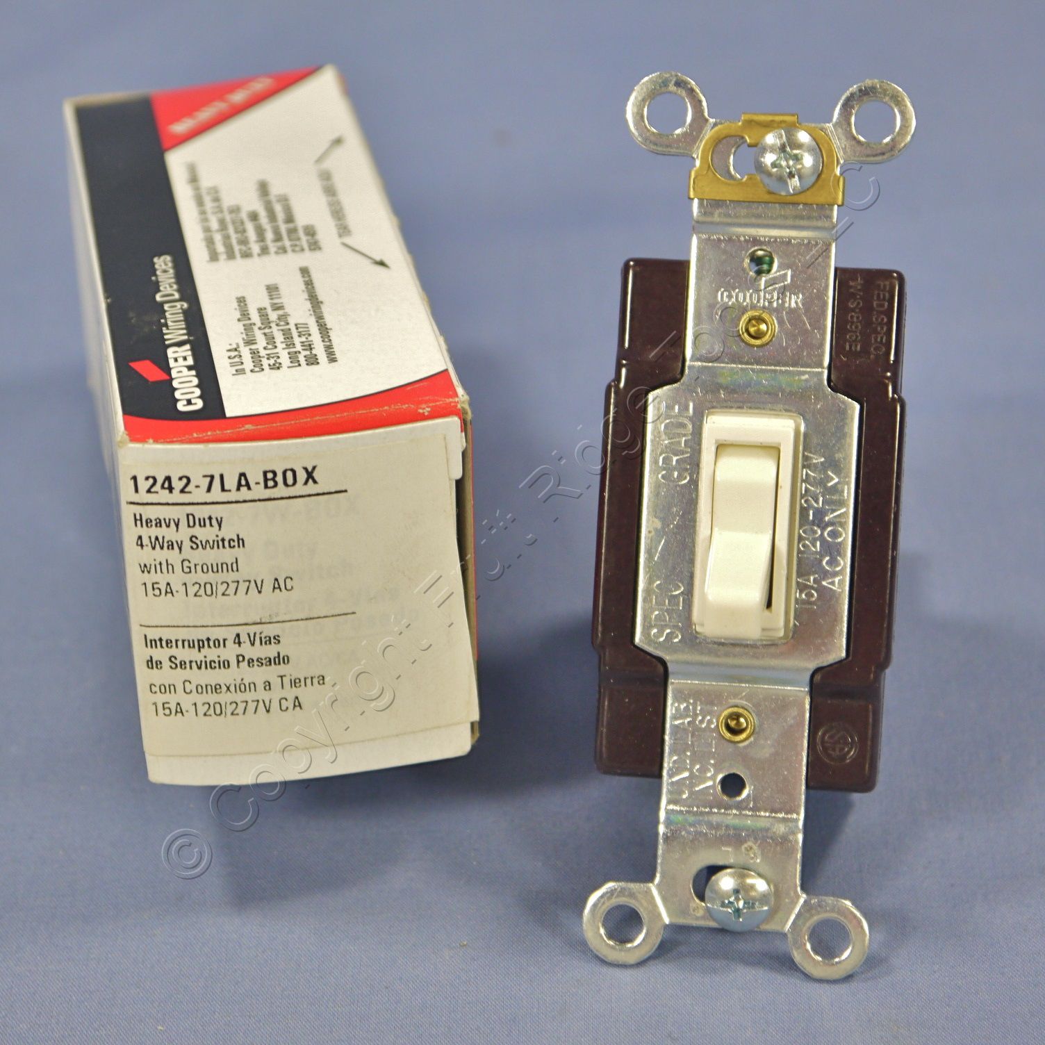
Cooper 4 way switch wiring diagram. 4 way switch wiring diagrams this 4 way switch diagram 1 shows the power source starting at the left 3 way switch. I would have to double check but im 90 certain the power is supplied at the entry level switch or it could be powered at the light. Remove the existing switch in the location where the sensor will be installed. To make this circuit work a 3 way dimmer can be used in place of one or both of the standard 3 way switches. The white wire becomes the energized. A wiring diagram is a simplified traditional photographic depiction of an electric circuit.
They all must be between the two 3 way switches. There are several ways to wire three way switches the key is to identify where the power source is. A 4 way switch wiring diagram is the clearest and easiest way to wire that pesky 4 way switch. 4 way switch diagram light between switches. Collection of leviton 4 way switch wiring diagram. Eatons 2019 revenues were 214 billion and we sell products to customers in more than 175 countries.
We provide sustainable solutions that help our customers effectively manage electrical hydraulic and mechanical power more safely more efficiently and more reliably. The 4 way switch is on the basement level and there is a 3 way switch in the entry and at the top of the steps on the main floor. A 4 way switch is always placed in between two 3 way switches. We have approximately 95000 employees. You can have an indefinite number of 4 way switches in a circuit. The sensor black wire will connect to either one of the black wires in the wall box.
Eaton switches are designed with a host of features that save time and labor and are thoroughly tested to ensure reliable electrical and mechanical performance. Watch the 4 way switch video below and pay attention. 4 way switch wring diagram. The sensor may be placed at either end of the 3 way circuit. For 3 way applications wire the sensor switch according to wiring diagram 2a or 2b using the wire nuts provided. Eaton 4 way switch wiring diagram.
Three wire cable runs between all the switches and 2 wire cable runs to the light. If you understand how to wire a 3 way switch youll have no issues with a 4 way switch. This is the wiring for a dimmer in a 4 way circuit. It is important to understand how these switches are wired before attempting to troubleshoot or replace. This 4 way switch diagram 2 shows the power source starting at the fixture. 4 way switch configurations are used to control lights with three or more switchesa 3 way switch is used on each end with one or more 4 way switches in between the two 3 way switchesthey do not have an onoff position like single pole switches.
4 way dimmer switch wiring diagram. I have a few of the most common ways in wiring a 4 way switch to help you with your basic home wiring projects.


