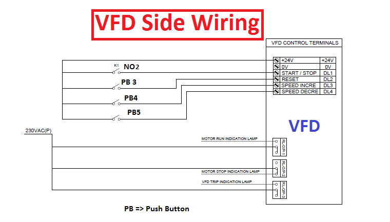
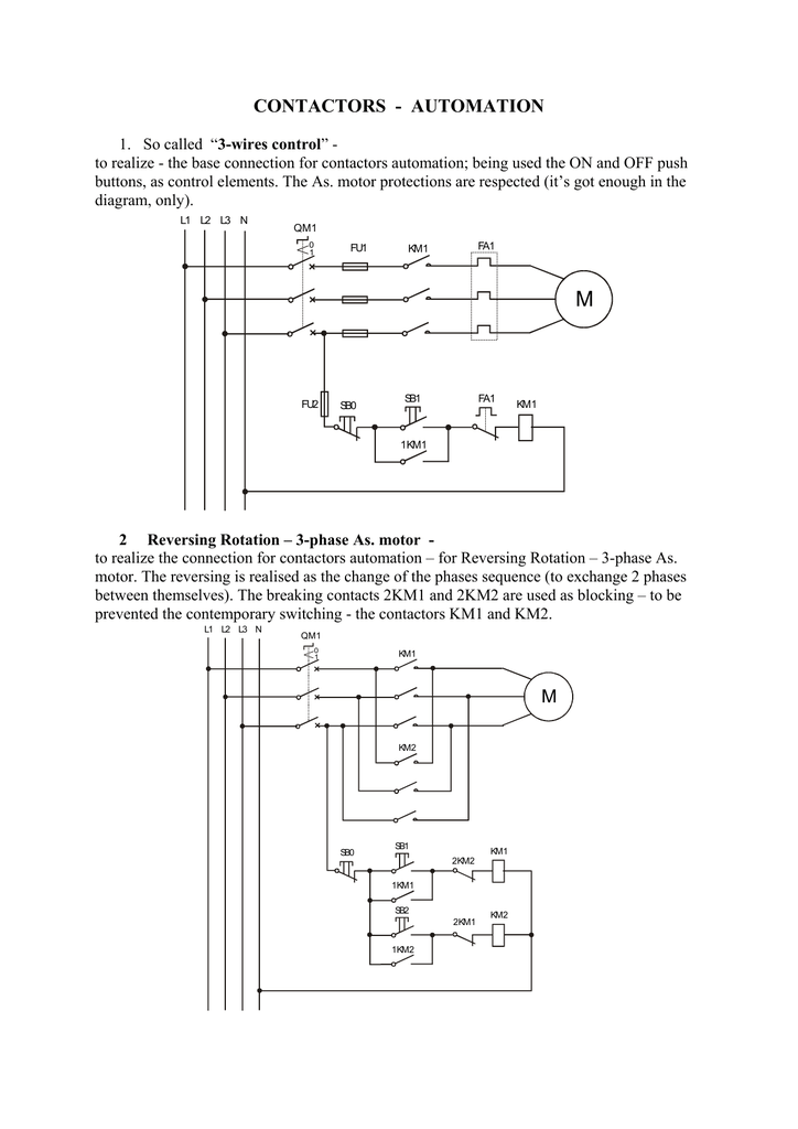
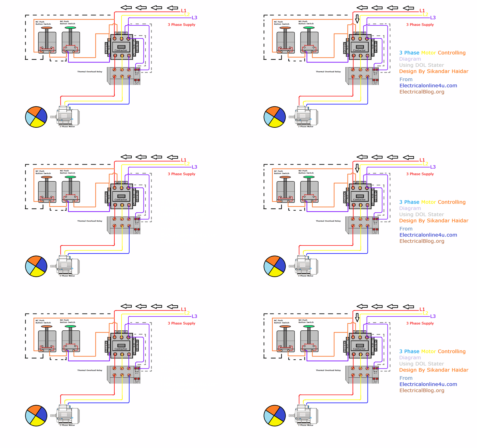
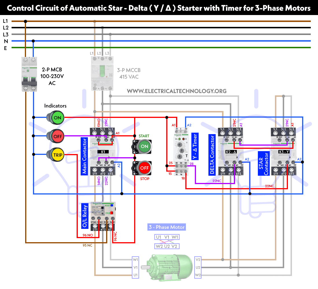
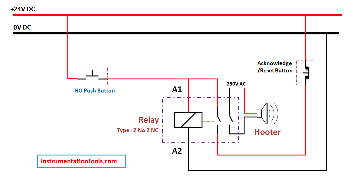
Push buttons shown in figure 1 are the most common type of control devices found in industrial facilities. On delay timer circuit diagram wiring diagram contactor with push button circuit diagram of delay timer on off power off delay timer circuit diagram 2 way lighting circuit triggering transformer push button fan switch light activated switch circuit diagram wd081 text.
Plc Plc Ladder Plc Ebook Plc Programming Typical Circuit
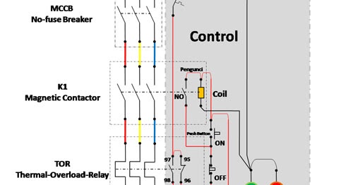
Contactor with push button on off control diagram. Study the contactor manufacturer information. The may be 2 or more sets of output contacts identified. Almost all industrial machines contain push buttons even if the facilities operation is to set to run automatically. Easy and simple wiring diagram to make you learn easily watch the video and subscribe my youtube channel air. Typical push buttons are momentary meaning they are designed with a spring to keep the button contacts open or closed at all times. For push button control stations 5 explanation of symbols momentary contact push button auxiliary contacts operate when operating coil of contactor.
I need help wiring my shaper. Releasing f normally open no contacts close forward f fast. Dol starter control and power wiring by using a fuse contactor overload relay motor. Contactor 1 will energise the 3 motor windings on one end of the motor while contactor 3 will bridge together the cables from the other side of the motor windings 45 and 6. On the machine there is a momentary type push button onoff switch the wiring appears to be in the main housing with the oil and gears but i cannot. These contacts may be indicated on the label as normally open no and normally closed nc.
The manufacturer information will identify the 2 input pins for 120 volts ac control. Here is what i have a 16 g e shaper with a 5hp 3 phase motor. This is star mode running 230 volts per winding see fig 4. In the above one phase motor wiring i first connect a 2 pole circuit breaker and after that i connect the supply to motor starter and then i do cont actor coil wiring with normally close push button switch and normally open push button switch and in last i do connection between capacitor. Each component should be placed and linked to other parts in particular manner. If you are interested to learn the working and connection of magnetic contactor by on and off push button here is a quick guide for you to learn inside a contactor part1.
Depressing button opens and parent switch does. Previous owners cut and removed the contactor. The above diagram is a complete method of single phase motor wiring with circuit breaker and contactor. When the start button is pressed contactor 1 and 3 will close. In this casem main line s slow closes lower contacts.


