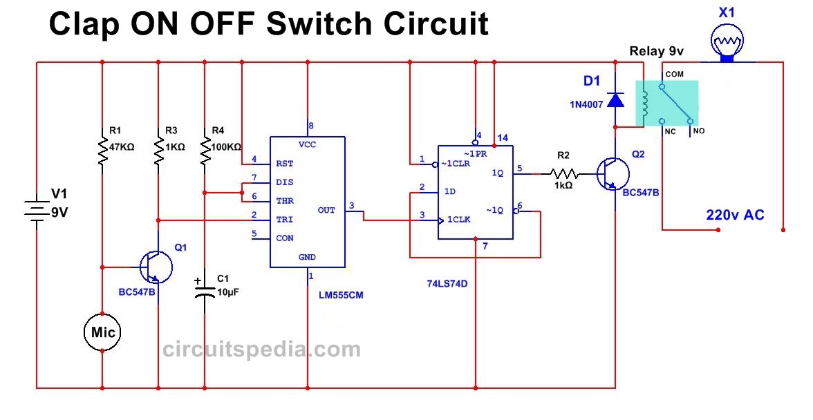
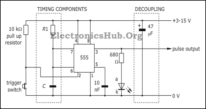
If we remove the d type flip flop from the circuit the led will be turned off automatically after some time and this time will be 11xr1xc1 seconds which i have explained in my previous circuit of clap switch. Clap switch is an interesting hobby circuit which turns on the lights with a clap sound.

Basic Electronics Projects And Tutorials Clap Based
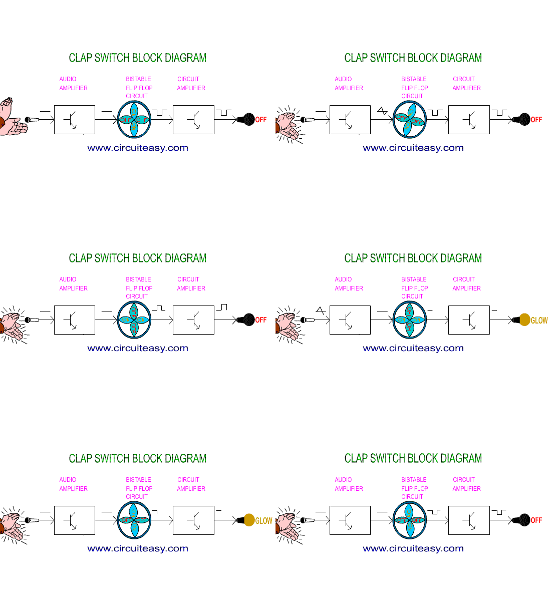
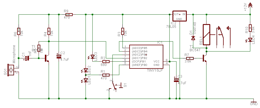
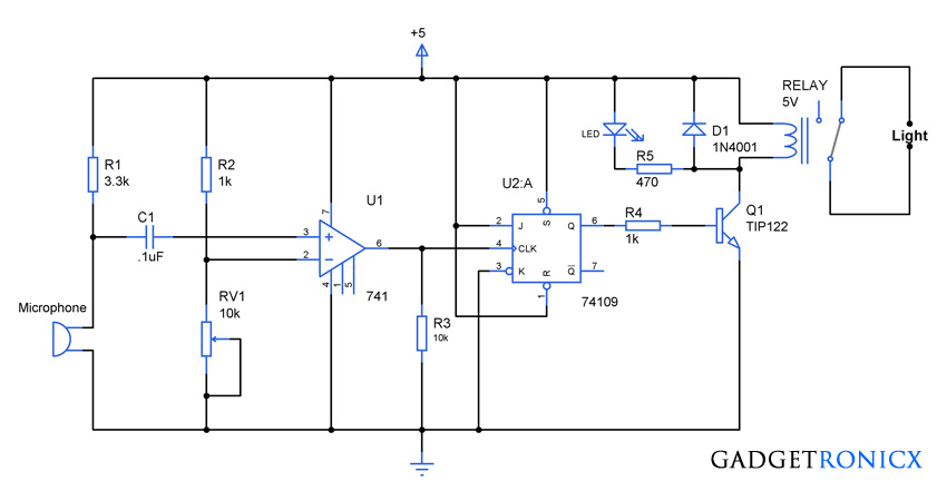
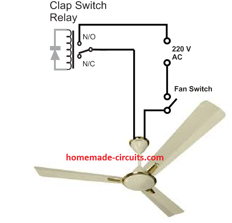
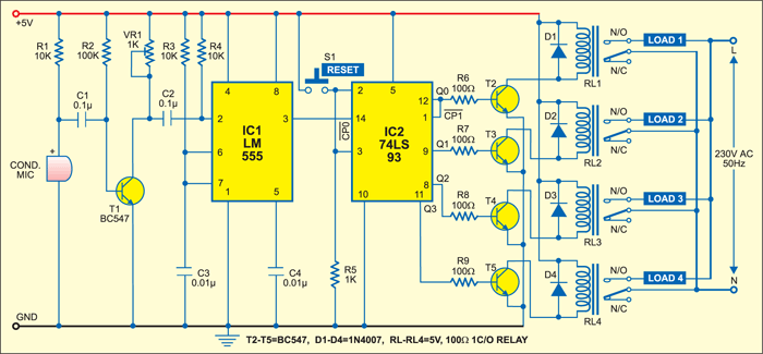
Clap switch circuit diagram. Clap switch circuit using 555 and 4017. Similarly when 555 timer generates. Clap switch circuit is a basic electronics project made from the basic components such as ic 555 timer bc 547 transistors led resistors capacitors etc. In the first circuit i will control a single relay using clap switch. When you clap once the relay is activated and the light or any load is turned on. Working and schematic diagram of clap swith circuit.
It gets back to its original state when an external clock pulse is given to a monostable oscillator. The entire function of the clap switch is based on cd 4017 ic and ne 555 ic. Clap switch circuit diagram. Ic 555 is a timer ic. Although its name is clap switch but it can be turned on by any sound of approximately same pitch of clap soundthe main component of this clap switch circuit is the electric condenser mic which has been used as a sound sensorcondenser mic basically converts sound energy into electrical energy. Now you can make a simple clap switch project here you can find all required components circuit diagram working process along with output video.
It is similar to an oscillator like monostable which has only one stable state. So this is the clap switch which will turn on with first clap and turn off with the second clap. When you clap for the second time the relay is deactivated and the light is turned off.
